

Exercise 6: Box, overlapping edges
This exercise was carried out with version 27.0 (Vertex 2021).
In this exercise you will learn to
-
We will become familiar with the options for the Add Flange feature.
-
To model the overlapping edge. (Excessive thickness has been used in the model to make the example figures clearer).
Functions to be used:
-
Sketching + Operation: Thin feature.
-
Add Flange, without Trim edges.
Create a new part
-
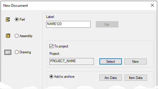
File > New > Part.
-
Enter the label (which is also the name of the model and by default will be the name of the drawing).
-
Enter the archive information by clicking Arc.Data.
-
Select the project where the model will be saved.
-
OK.
-
Model the bottom of the box
-
Size: 160*120*2
-
See instructions for Exercise 1: How to start modeling sheet metal.
Add flanges to long edges
-
Select two long lines from the top of the sheet.
-
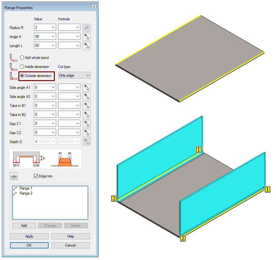
Right-click function: Add Flange.
-
Radius R: 2
-
Angle A: 90
-
Length L: 60
-
The other values: 0
-
-
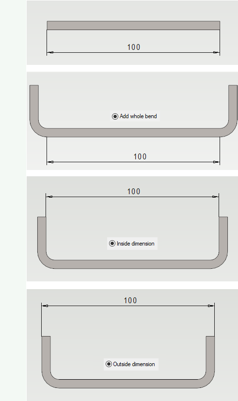
Click the option: Outside dimension.
The example in the figure below has a 100mm wide base with options:
-
Add whole bend.
-
Inside dimension.
-
Outside dimension.
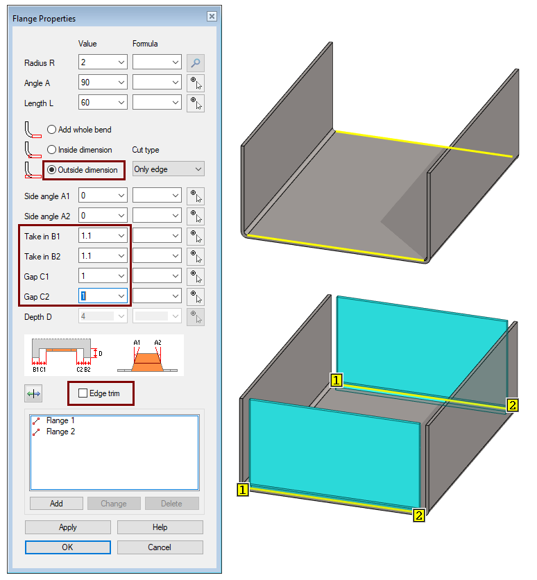
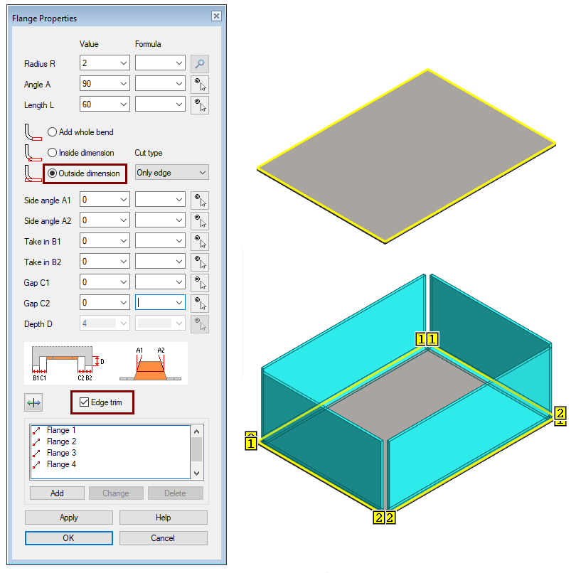
Add flanges to short edges
-
Select two short lines from the top of the sheet.
-
Right-click function: Add Flange.
-
Radius R: 2
-
Angle A: 90
-
Length L: 60
-
Take in B1 and B2: 1.1 (This value makes room for the overlapping flanges of the next step together with the values of the gaps C1 and C2.)
-
Gap C1 and C2: 1 (This value allows for reasonable manufacturability).
-
Side angle A1 and A2: 0
-
-
Click the option: Outside dimension.
-
Remove selection: Edge trim.
-
OK.
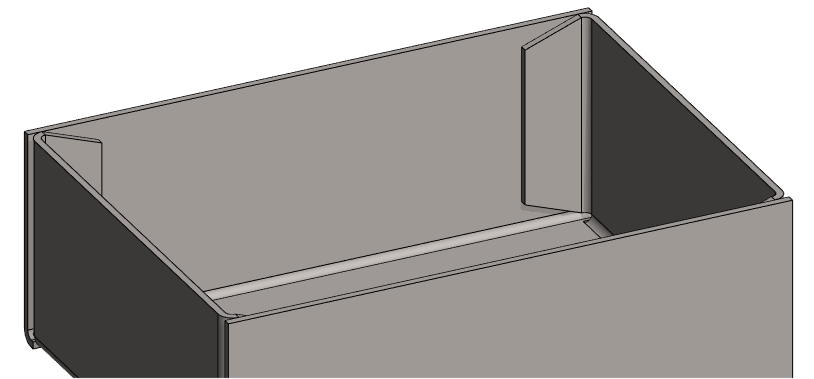
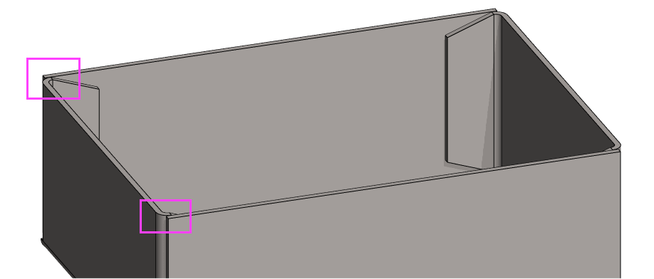
Add overlapping flanges
-
Click on the edges inside of the ends (4 pcs).
-
Right-click function: Add Flange.
-
Radius R: 2
-
Angle A: 90
-
Length L: 20
-
Side angle A1 and A2: 20
-
The other values: 0
-
-
Click the option: Add hole bend.
-
Remove selection: Edge trim. (If selected)
-
OK.
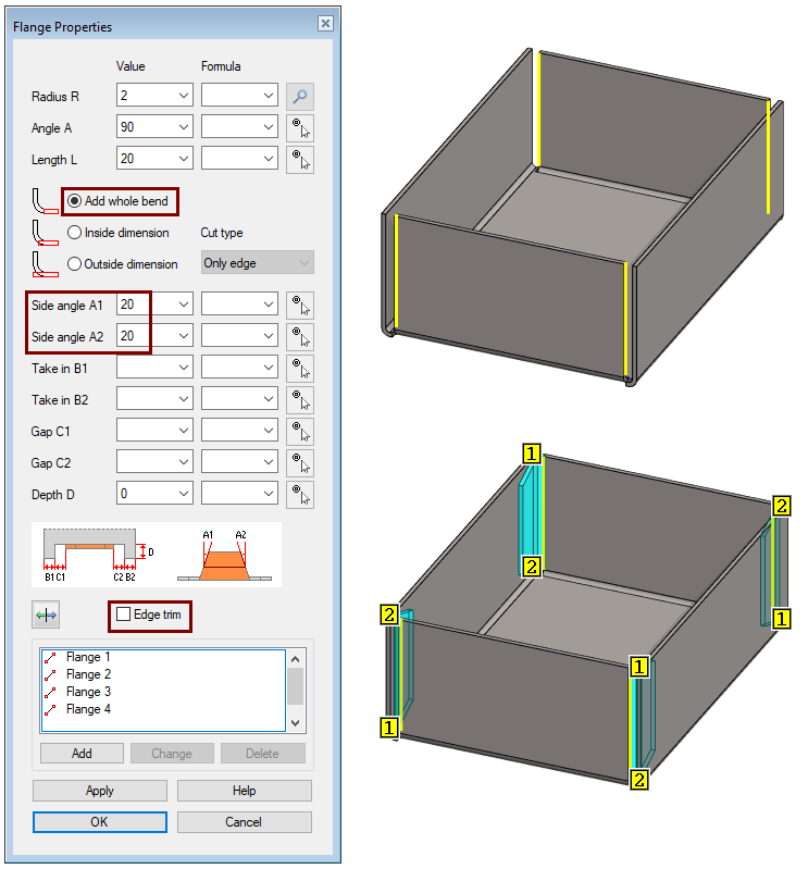
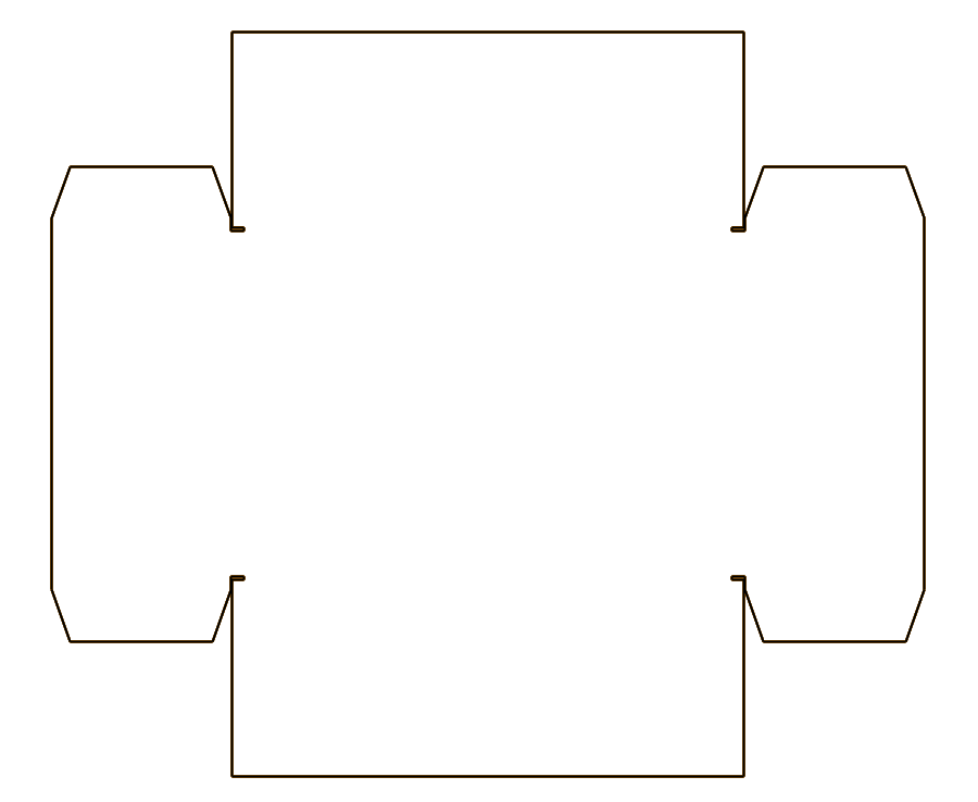
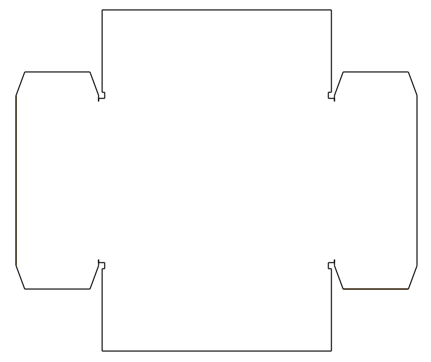
Create an unfold Drawing
-
In the feature tree, click Drawings.
-
Right-click function: New Drawing.
-
Select projections (here only: flatten sheet).
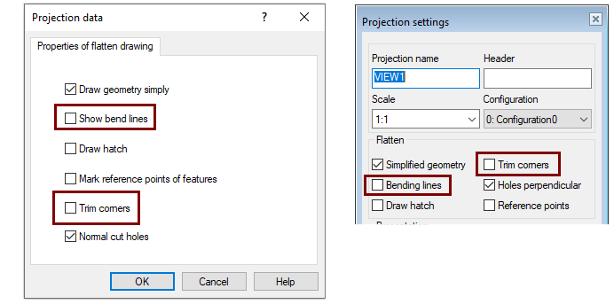
Select the options you want for flatten sheet projection
Another way
-
Trimming long sides is different, than above.
-
Here is one step less, than above.
Model the flanges of the box
-
Click to the top face of the plate or click all four lines of the top face.
-
Right-click function: Add Flange.
-
Radius R: 2
-
Angle A: 90
-
Length L: 60
-
The other values: 0
-
-
Click the option: Outside dimension.
-
Note the option: Edge trim.
-
OK.
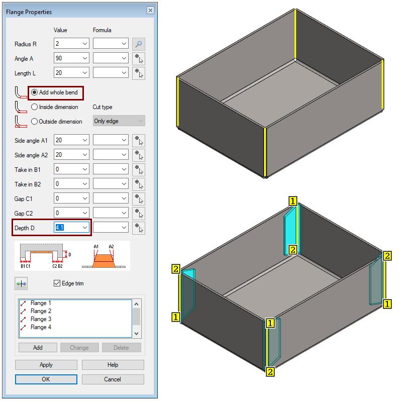
Add overlapping flanges
-
Click on the edges inside of the ends (4 pcs).
-
Be careful to choose the right line from the corner, because the lines on each side are 0.17mm apart.
-
-
Right-click function: Add Flange.
-
Radius R: 2
-
Angle A: 90
-
Length L: 20
-
-
Click the option: Add hole bend.
-
Side angle A1 and A2: 20
-
Depth D: 4.1 (4.1 = 2+2+0.1 = Sheet metal thickness + bending radius + working margin)
-
The other values: 0
-
-
OK.
Create an unfold Drawing
-
In the feature tree, click Drawings.
-
Right-click function: New Drawing.
-
Select projections (here only: flatten sheet).
Select the options you want for flatten sheet projection
Save the model
-
File > Save or click


Further processing of the model (These are presented in Exercise 5 "Drawing on model")
You can add a material item to the model with the right-click function Item Data.
-
These will also appear in the parts list of the model drawing.
You can create a drawing for the model:
-
In the feature tree, select Drawings.
-
Right-click function: New Drawing.
Video
Duration 1m 20s
For the best quality for your video, watch it:
-
In full screen mode.
-
With a resolution of 1080pHD.