

Exercise 4: Bottle opener
This exercise was carried out with version 27.0 (Vertex 2021).
In this exercise you will learn how to
-
Use the library feature at the beginning of the model.
-
To change a part to sheet metal part and enter the thickness by clicking.
-
To bend the plate.
-
Add a body as a feature.
-
Model the slot (Sketch + Cutout Extrusion).
-
Change the part into a sheet metal part.
-
Create Bending 1 (One line in the scetch + opetarion: Bend).
-
Create Bending 2 (One line in the scetch + opetarion: Bend).
Functions to be used:
-
Add a feature and variate it before adding.
-
Sketching + operation: Cutout > Extrude.
-
Sketching + operation: Bend
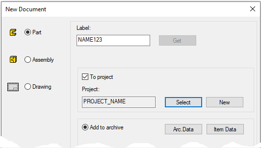
Create a new part
-
File > New > Part.
-
Enter the label (which is also the name of the model and by default will be the name of the drawing).
-
Enter the archive information by clicking Arc.Data.
-
Select the project where the model will be saved.
-
OK.
-
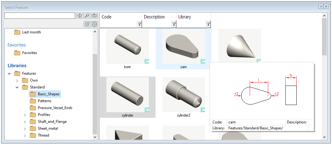
Start modeling by adding a library feature
-
The function: Library feature > Boss (in the ribbon) or Right-click function: Library feature > Boss.
-
Find the feature: Standard > Basic_Shapes > Cam.
-
Double-click the feature.
-
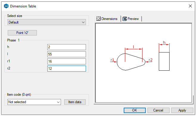
Dialog Dimension Table opens.
-
-
Enter the dimensions of the feature:
-
h = 2
-
l = 55
-
r1 = 16
-
r2 = 12
-
-
OK.
-
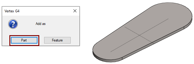
The program asks if you want to add geometry as a part or feature.
-
Click the Part.
-
The feature falls from its own origo to the origo of the model.
-
When you add a feature to an empty part model, the program asks if you want to add the feature as part or as a feature.
-
As Part = Geometry comes with a complete history of the part. You can edit all features and their drafts, and you can also delete features.
-
As Feature = The geometry appears in the feature tree as one step. You can only vary it using the dimension table (that is, the dimensions that have the formula can be changed)
If you are adding geometry as a feature, select the location of the feature.
Convert the type of part to sheet metal part
-
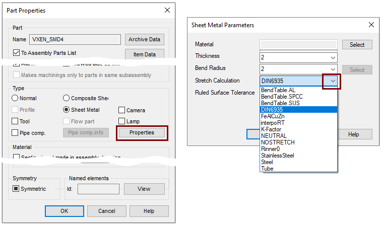
Right-click function: Properties. (When nothing is selected).
-
Change the type: Sheet Metal.
-
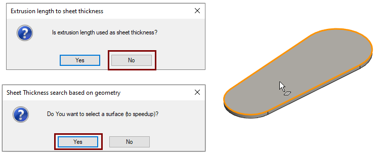
The program asks the question: Is extrusion lenght used as sheet thickness?.
-
-
Answer the question: No. Because in theory it could be uncertain whether the value of extrusion of a part would be valid for sheet metal thickness.
-
The program asks the question: Do You want to select a surface (to speedup)?.
-
-
Answer the question: Yes.
-
Click the face on which the program estimates the thickness of the sheet metal.
-
Click Properties.
-
Select the Stretch calculation method.
Model the perforation
-
Select the top face.
-
Right-click function: New Sketch > To Face.
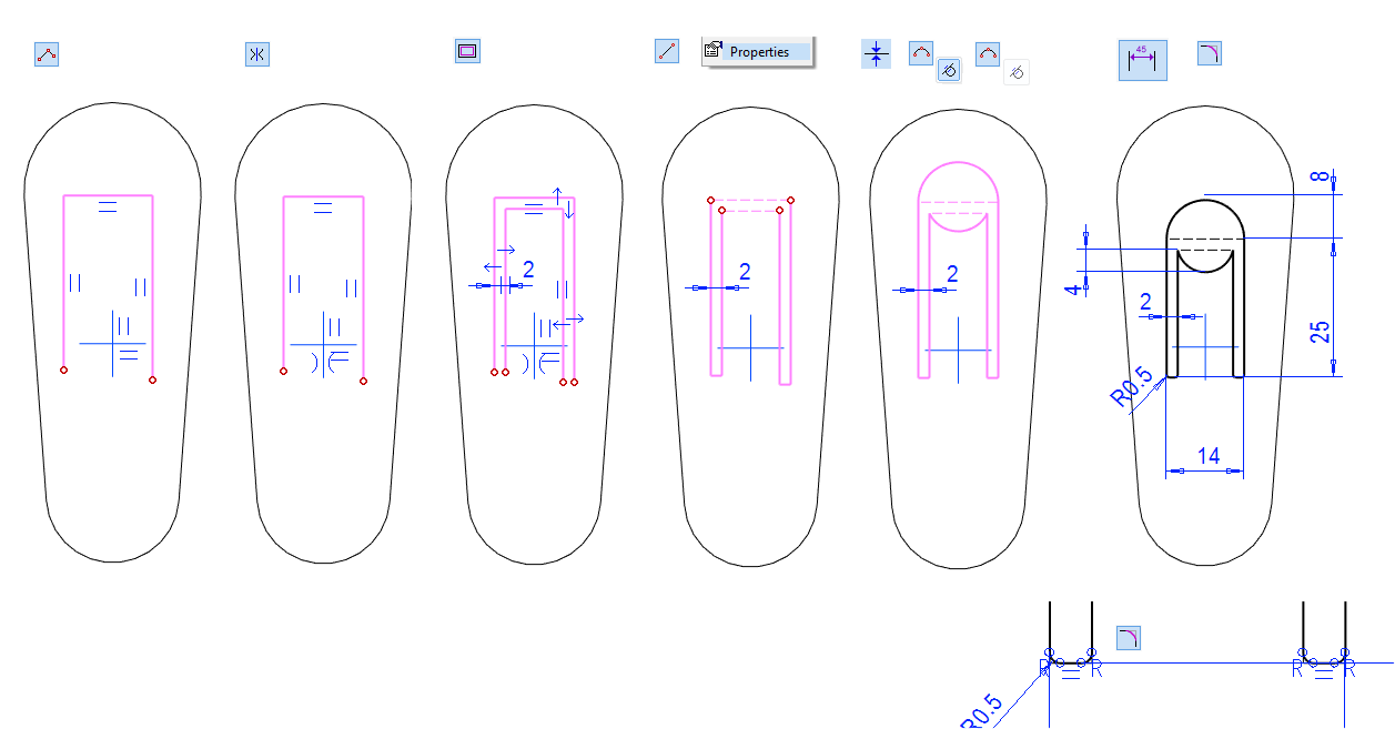
Sketch the shape
-
The Function: Polyline.
-
Add the Symmetry constrain between the vertical lines and the center cross.
-
Create offset lines.
-
Close shape (The function: Two Point Line.)
-
Convert style of horizontal lines to the Construction line.
-
Sketch the arches.
-
Dimension the sketch.
-
Create roundings in the lower corners (0.5).
-

Operation
-
Cutout > Extrude.
-
Thru All.
Model the first bending
-
Select the underside of the model.
-
Right-click function: New Sketch > Face.
Sketch the shape
-
Sketch one line from the edge of the tab to the other.
-
Add the Distance constraint: 4.
-
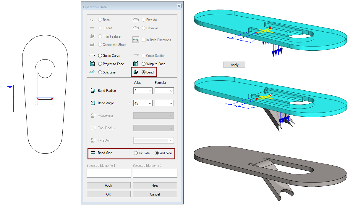
Operation
-
Bend
-
Bend Radius: 3.
-
Bend Angle: 45.
-
Bend Side: Make sure that the Bend side is as shown. If not, change it by selecting 1st Side or 2nd Side.
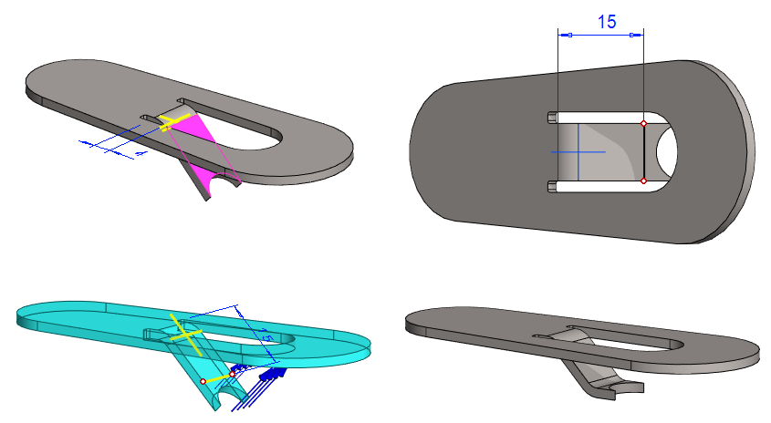
Model the second bending
-
Select the face shown in the figure.
-
Right-click function: New Sketch > Face.
Sketch the shape
-
Sketch one line from the edge of the tab to the other.
-
Add the Distance constraint: 15.
-
Operation
-
Bend
-
Bend Radius: 3.
-
Bend Angle: 45.
-
Bend Side: Make sure that the Bend side is as shown. If not, change it by selecting 1st Side or 2nd Side.
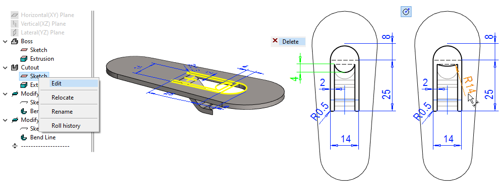
Edit the sketch of perforation
The radius of the tab head is incorrect. Change its dimensions criteria.
-
Select the sketch of perforation feature from the feature tree.
-
Right-click function: Edit.
-
Delete the dimension 4 (shown in green in the figure).
-
Add the Radius constraint with value of 14 (shown in orange in the figure).
-
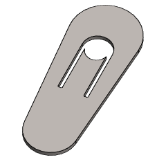
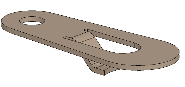
In the figure below is an opener that has been given visualization material
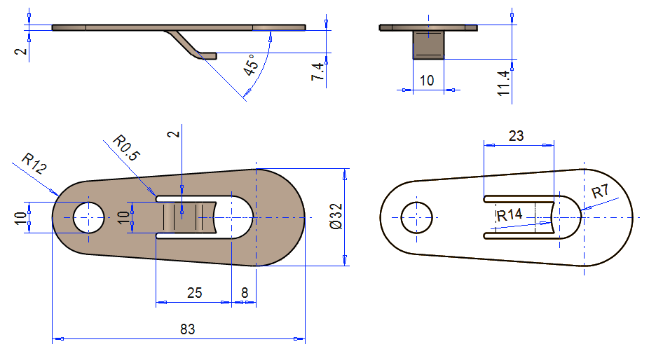
The figure below shows a drawing with three main projections and flatten sheet projection.
Save the model
-
File > Save or click


Video
Duration 2m 21s
For the best quality for your video, watch it:
-
In full screen mode.
-
With a resolution of 1080pHD.