

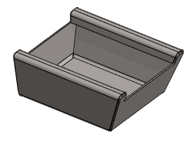
Exercise 3: Diagonal Box
This exercise was carried out with version 27.0 (Vertex 2021).
In this exercise you will learn to
-
To model a part that is suitable for modeling a sheet metal part with the tangential offset function.
-
How to convert a closed part (blob /jig) into a sheet metal part with the function surface chain offset.
-
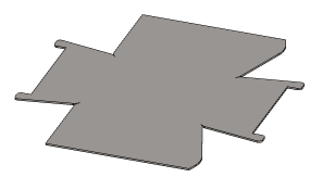
How to unbend a 3D model.
-
To create corner openings with library features.
-
To bend the modified part back into the housing from the unfolded state.
-
Model a rectangular prism (Sketch + Boss > Extrusion).
-
Create the drafts.
-
Remove the material from the top surface (Sketch + Cutout > Extrusion).
-
Create the necessary roundings.
-
Create a tangential offset.
-
Unbend the part.
-
Trim the corners (in two different stages).
-
Bend the unbend part back into the housing form.
Functions to be used:
-
Sketching + operation: Boss > Extrude.
-
Draft.
-
Add Round/Bevel > Single Edge Round.
-
Tangential offset.
-
Trim corner.
-
Unbend.
-
Rebend.
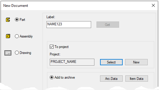
Create a new part
-
File > New > Part.
-
Enter the label (which is also the name of the model and by default will be the name of the drawing).
-
Enter the archive information by clicking Arc.Data.
-
Select the project where the model will be saved.
-
OK.
-
Create the first feature
-
New Sketch > To horizontal (XY) plane.
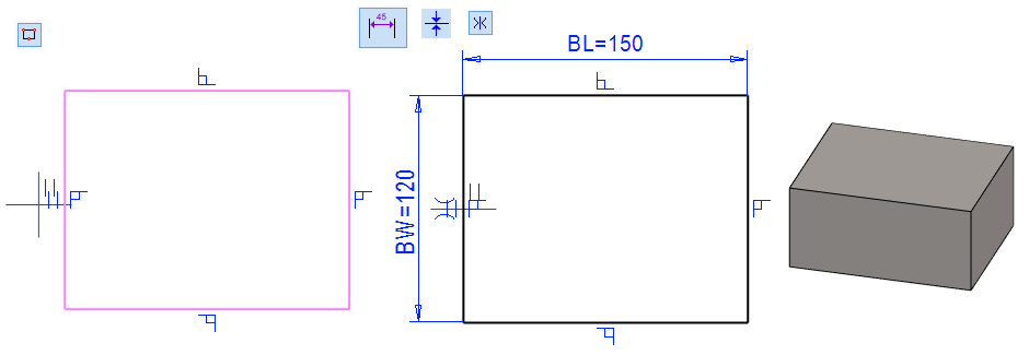
Sketch the shape
-
The function: Rectangle.
-
Add the Coincident constraint between the left vertical line and the center mark (origo).
-
Add the Symmetry constraint between the horizontal lines and the center mark (origo)
-
Add the Dimension constraints and formulas for them.
-
Length: 150 and the formula, eg BL (Length of the box).
-
Width: 120 and the formula, eg BW (Width of the box).
-
-

Operation
-
Boss > Extrude
-
Length: 70 and the formula, eg BH (Height of the box).
Create first drafts
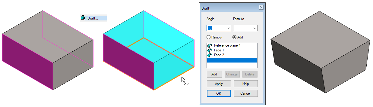
Create the Drafts on the long sides first so that the dimension of the bottom is maintained and then make the Draft on the end face on the right side so that the dimension of the bottom is maintained.
-
Click both long page (Remember the Ctrl key).
-
Right-click function: Draft.
-
Click to the bottom of the part as the reference level (whose dimensions do not change).
-
In the Dialogue: Draft.
-
Angle: 10.
-
Add.
-
-
OK.
The dimensions of the part remain at the clicked reference level.
-
Remove = Remove the geometry from the reference level.
-
Add = Add the geometry from the reference level.
Create the second Draft
-
Click to the right end.
-
Right-click function: Draft.
-
Click to the bottom of the part as the reference level (whose dimensions do not change).
-
In the Dialogue: Draft.
-
Angle: 20.
-
Add.
-
-
OK.
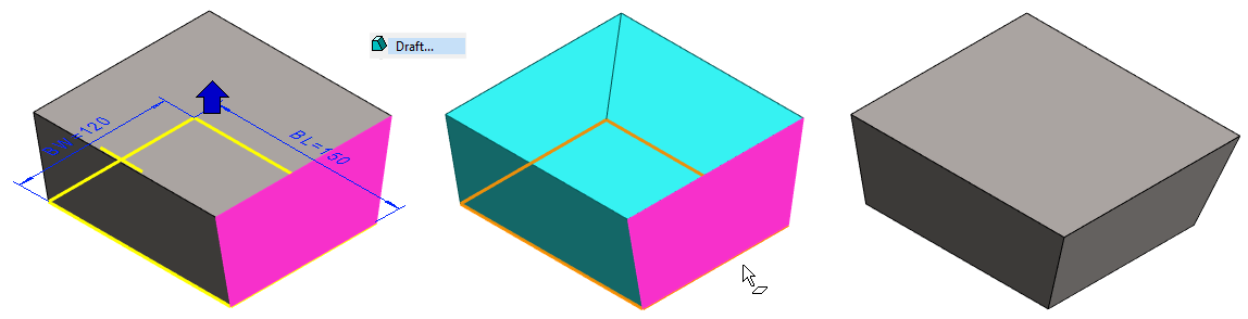
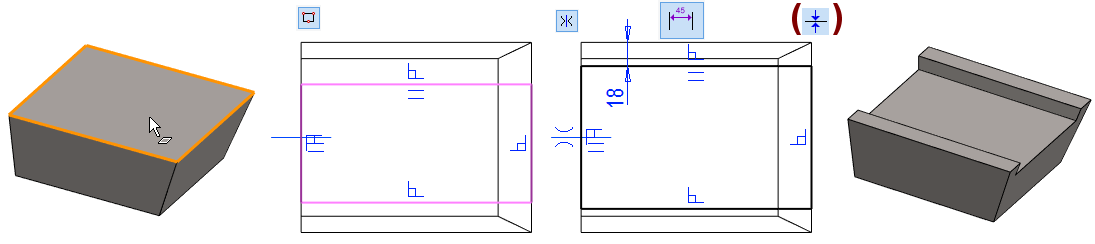
Create a hole in the top
-
Select the front face.
-
Right-click function: New Sketch > Face.
Sketch the shape
-
The function: Rectangle.
-
Start sketching from the left vertical line.
-
-
Add the constraints:
-
The Symmetry to horizontal lines with respect to the central cross.
-
The Distance (18) as shown in the figure.
-
The Conincident between the vertical line of the sketch on the right and the vertical line of the part shown below. (If needed).
-
Operation
-
Cutout > Extrude
-
Length: 15
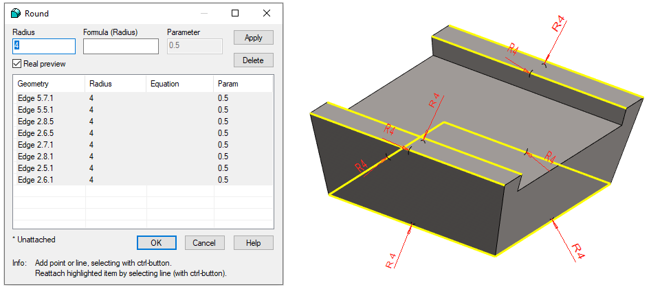
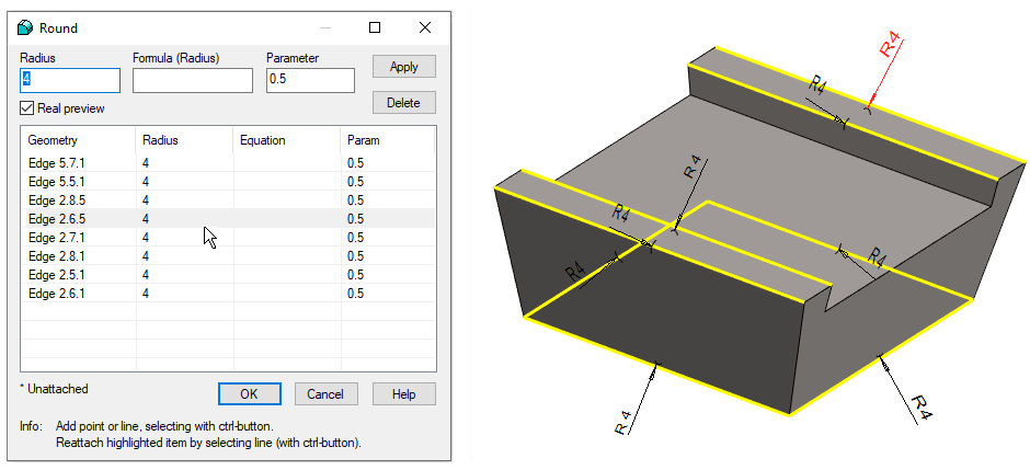
Create roundings on the edges over which the plate bends
-
Select the four edges of the bottom and the four edges of the top (the yellow lines shown in the figure).
-
Right-click function: Add Round/Bevel > Round (or Single Edge Round).
-
Enter the radius: 4.
-
Even if the rounds shown in the list have an old default value, pressing the OK button will give the value in the Radius field.
-
-
OK.
Create roundings at edges where the plate is bending over. Leave the roundings off at the corners where the edges of the plates become.
-
The Tangential offset function does not require it.
-
In order to create an unbend, the edges to be rounded must be selected according to the above rule.
The size of the rounding is determined by whether you have modeled the incoming sheet metal part according to the outer and inner dimensions.
-
If you modeled the part based on the external dimensions, give the radius of the corners as the material thickness of the sheet metal + the inner radius (i.e. the radius of the bending response or bending blade).
If you would like to enter one edge a different rounding value, follow these steps.
-
First, enter the most common rounding value in the Radius field.
-
Click Apply.
-
Select the rounding you want to change.
-
Click dimension (in the Working window) or
-
Click the correct line in the dialog. The dimension of the rounding corresponding to the selected row remains red when the other dimensions are drawn in black.
-
-
Enter a new rounding value in the Radius field.
-
Click Apply. (Or OK if you don't want to change the rounding of other edges)
-
Select the next rounding you want to change.
-
etc.
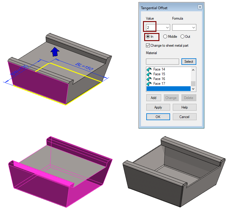
Create a sheet metal part
-
Click on the surface that will remain on the sheet metal part.
-
Right-click function: Tangential offset.
-
Specify the thickness of the metal sheet.
-
Enter the thickness value or
-
use the Select button to retrieve the material.
-
-
Select in which direction the material is added relative to the selected surface.
-
In = The part is modeled according to the internal dimensions of the box and the roundings are the internal radii of the bent plate.
-
Middle = a rare case where a material is added symmetrically to both sides of selected surfaces.
-
Out = The part is modeled according to the outer dimensions of the box and the roundings are the outer radii of the bent plate.
-
-
Accept the default: Change to sheet metal part.
-
OK.
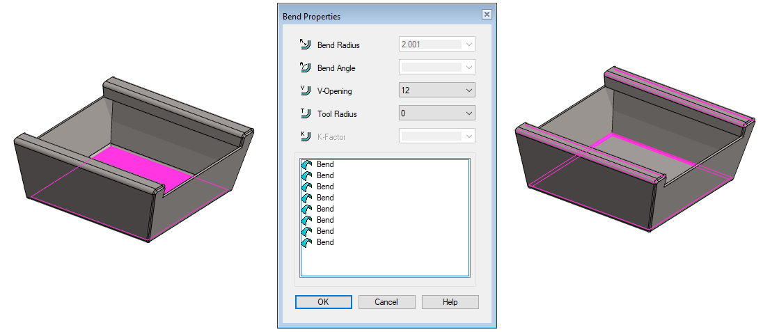
Create a 3D flattened sheet
-
The function: Unbend (in the ribbon) or Right-click function: Edit model > Unbend.
-
The program searches for the largest surface of the piece and stains it red and suggests that the unfolding be done accordingly.
-
If the face is valid, confirm it with OK or the V key or the middle mouse button.
-
If the face is invalid, click another face.
-
-
Depending on the selected Stretch calculation method, the program may display a dialog Bend Properties from which you can select other values if necessary.
-
But for method DIN6935, for example, no dialog will appear.
-
OK.
-
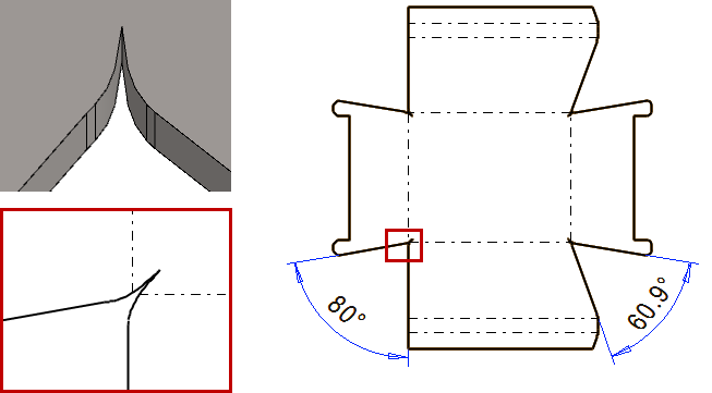
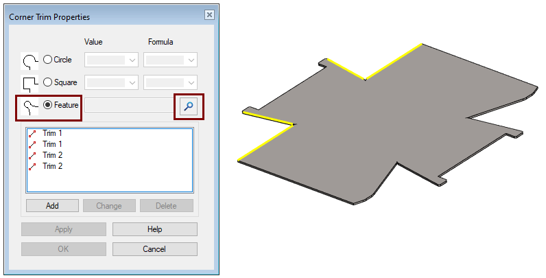
The Trim Corner function searches for all corners in the flatten sheet and suggests that similar openings be made for them.
Automatic corner trim of all corners is possible with all the different trimming tools provided by the program, for parts with equal corners.
This model has two different sized corners, so the Circle opening tool is valid, the others are invalid.
-
For this reason, in this model, corner trim must be made in two steps.
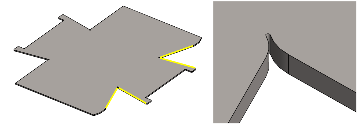
The sharp corner shown in the figure may cause problems when the part is cut with a laser machine.
-
For this reason, it is desired to reshape the corner.
Trim corners
-
The function: Trim corner (in the ribbon) or Right-click function: Edit model > Trim Corners.
-
Dialog Corner Trim Properties opens.
-
-
Click two lines from the corners of the same size.
-
Accept the selections (with OK or the V key or the middle mouse button.)
-
The selected lines appear in the list.
-
-
The program suggests trimming a circle, but change it to a Feature.
-
Click the magnifying glass button to access the feature library.
-
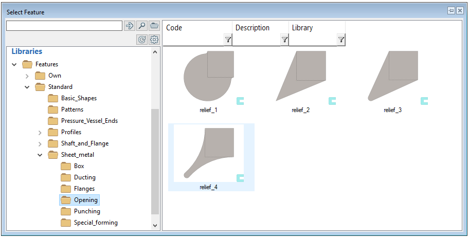
The Browser Select Feature opens
-
-
Click a library feature.
-
In this exercise, relief_4.
-
-
OK (in the dialog Corner Trim Properties).
-
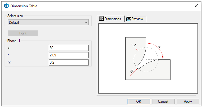
The Dialog Dimension Table opens.
-
-
If necessary, you can change the values in the Corner Trim tool
-
Change the values of the radii r and r2.
-
r = 3.3 (In this exercise)
-
-
Do not change the value of angle (a).
-
Do not change the value of the main circle (r) lower than suggested. If you did, the program would no longer agree to bend the part back to the housing shape.
-
-
OK.
-
The program generates a feature with given dimensions.
-
The program positions the feature in the corners and displays the situation.
-
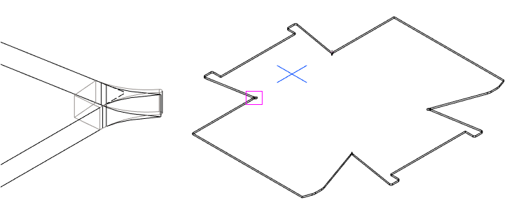
Trim the corners at the other end of the piece.
-
Note that you use at least the same radius (r) in the latter pair of corners as in the first pair of corners, otherwise the machining will not extend deep enough inside the part and the rebend will be prevented.
-
r = 3.3 (In this exercise)
-
-
In those parts with different angles between the flanges, the r-value should be somewhat larger than the default, otherwise rebend will fail.
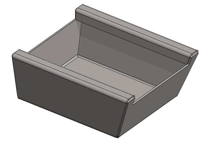
Re-bend the part
-
The function: Rebend (in the ribbon) or Right-click function: Edit model > Rebend.
If rebending is not successful, enter the values of the corner trimming tool (r and maybe r2) larger.
-
Remove the old feature rebend.
-
Edit Corner Trim features.
-
For this model, the r-value must be at least 3.3 mm for successful rebending.
-
Edit the values for both features if rebend does not work.
-
-
Unfortunately, the program does not remember previously entered values, but presents the original default values.
- 
Save the model
-
File > Save or click


Further processing of the model (These are presented in Exercise 5 "Drawing on model")
You can add a material item to the model with the right-click function Item Data.
-
These will also appear in the parts list of the model drawing.
You can create a drawing for the model:
-
In the feature tree, select Drawings.
-
Right-click function: New Drawing.
Video
Duration 2m 12s
For the best quality for your video, watch it:
-
In full screen mode.
-
With a resolution of 1080pHD.