

Exercise 2: Box
This exercise was carried out with version 27.0 (Vertex 2021).
In this exercise you will learn to
-
Add a flange.
-
Trim an edge
-
Enter material information.
-
Create drawing with flattened (unbent) projection.
-
Sketch the base and extrude it into a sheet (With the operation Thin feature).
-
Create flanges at the top edges of the base.
-
Create flanges on the outer edges of the vertical sides.
-
If necessary, modify the miter trim of the collar to a butt trim.
-
Enter the material information for the part, i.e. search for the raw material item.
-
Create a Flatten sheet drawing for the part.
Functions to be used:
-
Operation: Thin feature.
-
Add Flange.
-
Trim Edges (Automatically and manually).
-
Item Data.
-
Drawing > New Drawing.
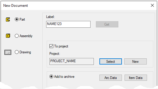
Create a new part
-
File > New > Part.
-
Enter the label (which is also the name of the model and by default will be the name of the drawing).
-
Enter the archive information by clicking Arc.Data.
-
Select the project where the model will be saved.
-
OK.
-
Create the first feature
-
New Sketch > To vertical (XZ) plane.
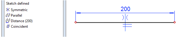
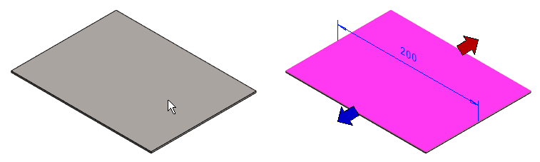
Sketch the shape
-
The function: Two-point Line.
-
First, select a point.
-
Then enter the dimensions 200. (and enter the formula if you want: eg LENGTH).
-
Add the Coincident constraint between the line and the center cross.
-
Add the Symmetry constraint between the ends of the line and the center cross.
-

Operation
-
Thin feature.
-
Length: 150
-
Sheet Thickness: 2
-
Model the flanges of the box
-
Click to the top face of the plate.
-
Right-click function: Add Flange.
-
The program selects all edges of face and opens the dialog: Flange Properties.
-
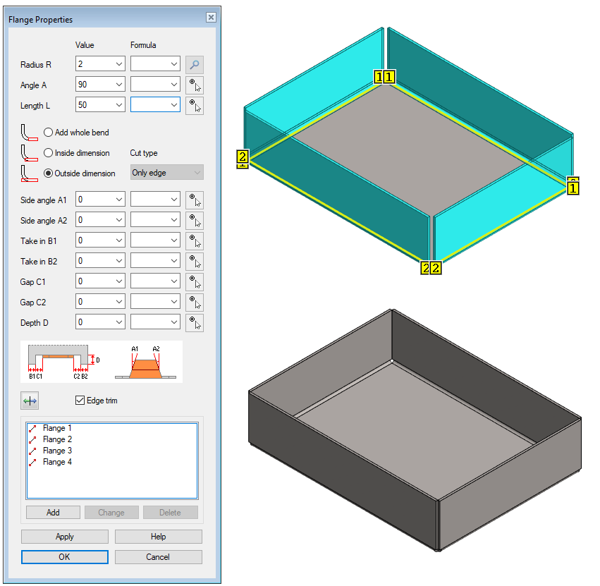
Enter the Flange Properties
-
Radius: 2 (The program suggests the thickness of the sheet metal plate).
-
Angle: 90 (The program suggests a previously entered angle).
-
Length: 50 (The program suggests a previously entered length).
-
Select Outside dimension (In this case, the size of the housing retains the previously given dimensions of 200 * 150mm.)
-
Keep selection Edge trim valid.
-
Radius R = The inner radius of the bend, i.e., describes the magnitude of the bending response or the rounding radius of the presser in the blade.
-
If not specified, then the radius is the same as the material thickness of the sheet metal.
-
-
Angle A = The angle of the flange with respect to the plate.
-
The angle can also be defined by clicking a line or a point.
-
More about this on the website: Sheet Metal Design 2018
-
-
Length L = The length of the flange at the intersection of the bottom of the plate and the edge of the flange
-
Way of bend. It is described in more detail both in the instructions and on the above-mentioned website.
-
Add whole bend = The outer dimensions of the part increase in the bending direction by the thickness and radius of the plate. That is, the area of the bottom face remains the original.
-
Inside dimension = The outer dimensions of the part increase in the bending direction only by the thickness of the plate. That is, the area of the bottom decreases by measure of the radii
-
Outside dimension = The dimensions of the part do not increase, so the dimensions of the base are reduced.
-
-
Side angle A1 and A2
-
The positive angle makes the edges of the flange taper.
-
The negative angle makes the edges of the flange expand.
-
-
Take in B1 and B2
-
The bending feature does not start from the beginning of the line (B1) or the end of the line (B2), but only by a given dimension from the end of the line.
-
-
Gap C1 and C2
-
Gap between flange and Take in. This only matters if the indentation B (Take in B) and Depth D of the flange are used.
-
-
Depth D = The flange does not start at the selected edge, but at a distance D from inside the body.
-
The direction of the flange can be changed using the arrow button

-
Below the box is a list of flanges.
-
You can assign the parameters to only one flange. Click the flange from the list and enter values. Then press the Apply before clicking any other flange.
-
You can add a new flange with the Add to the same history step.
-
You can remove the one flange, after clicking, with the Delete button.
-
Option 1: Modeling and trimming box top flange to miter corners
-
Select the outer corners at the top of the flanges
-
Right-click function: Add Flange.
-
Radius: 2 (The default for this part).
-
Angle: 90
-
Length: 20
-
Select Outside dimension (In this case, the height of the box remains 50mm. )
-
Keep option Edge trim valid.
-
OK.
The program adds horizontal 20mm wide flanges and makes automatic miter fillings in their corners.
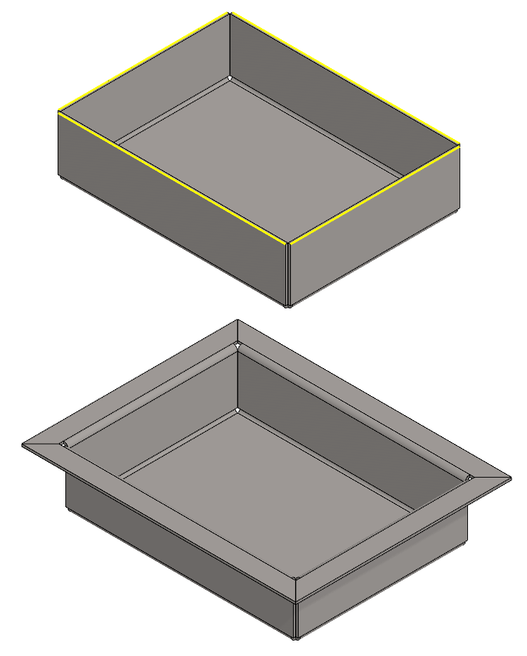
Option 2: Modeling the top flange of the box without trimming. After that manual trimming.
-
Select the outer corners at the top of the flanges
-
Right-click function: Add Flange.
-
Radius: 2 (The default for this part).
-
Angle: 90
-
Length: 20
-
Select Outside dimension (In this case, the height of the box remains 50mm. )
-
Remove the option: Edge trim.
-
OK.
Manual flange trimming
In this exercise, it is desired that the long edges be stretched and that the short edges be stretched close to the long edges.
-
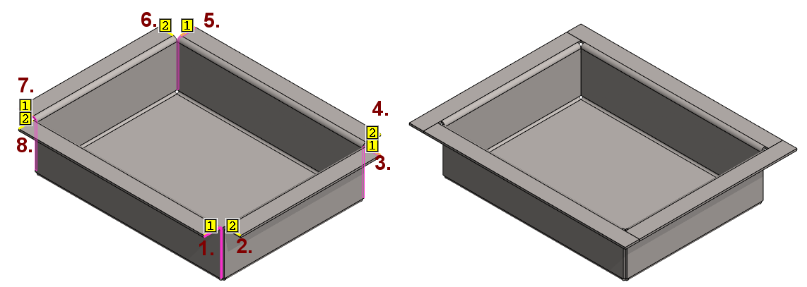
Select the top edges of the flanges (yellow lines in the figure).
-
The order in which the lines are clicked matter: From the corner, you first click the line of the edge you want to stretch
-
See the order in the figure: 1. and 2.
-
-
Right-click function: Trim edges.
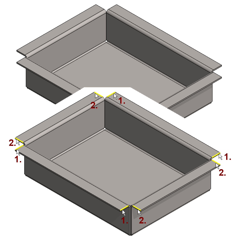
The dialog Edge Trim Properties is opened and program marks the corners to be trimmed.
-
Select option: Only other edge.
-
Edges that stretches is marked in purple.
-
Press the Apply to see how the trimming will take place if you accept the selections with OK.
-
OK, if you selected the edges in the correct order.
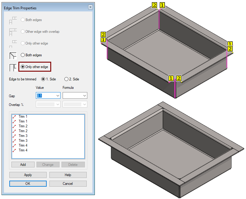
Below is a figure where the edges are clicked in order 1 ... 8
-
Note that the program suggests that each edge be stretched.
-
If you now accept the selections with OK, you will get "circulating flanges". Figure on the right.
-
Click a trim from the dialog list.
-
If the desired corner was selected, then select the side that stretches.
-
Click 1. Side or 2. Side.
-
-
Press Apply and slick the second corner that needs to be changed.
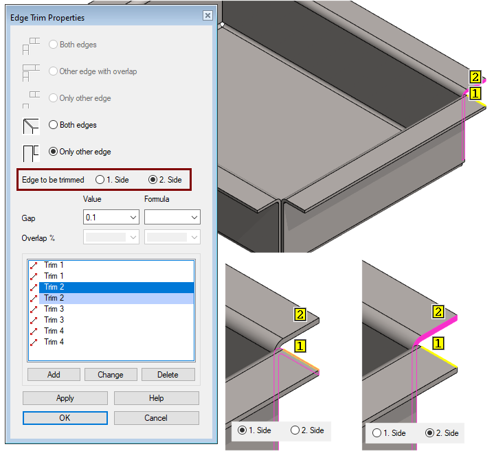
Both edges = Default trimming is miter.
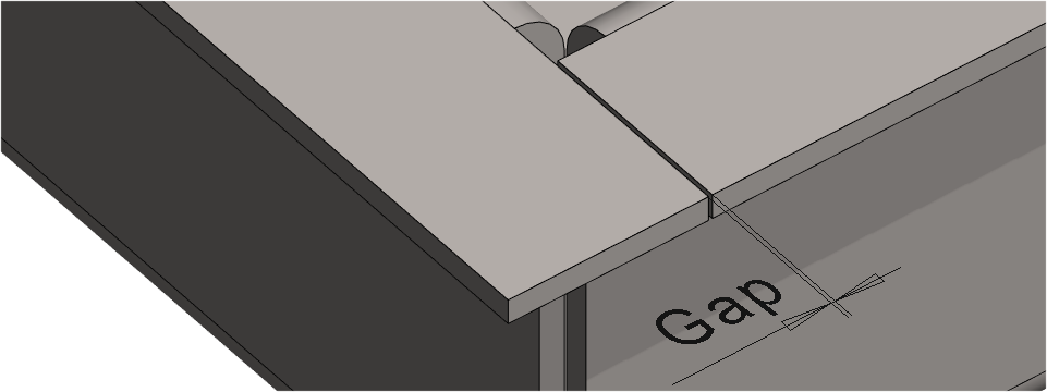
Only other edge = One edge extends to full length and the other to the end of the gap (default 0.1mm) from the previous one.
Gap = Default 0.1mm. Do not use a gap value of 0 (zero).
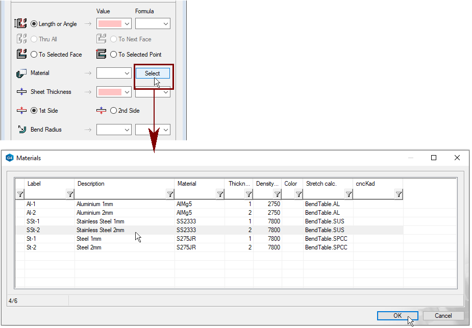
Entering raw material with Thin feature operation:
When you make a sheet metal from the first sketch (Operation: Thin feature), then you can also select the raw material.
-
Press Select.
-
Click a row.
-
OK.
If you use this method to select a raw material (Item Data), at the same time you define:
-
Stretch calculation method.
-
The identifier of the item (raw material).
-
Set the thickness of the plate.
-
A density is also added, which can then later be used to calculate the weight of the part.
Items used as raw material for sheet metal must be added to the Materials data base to find them behind the Select button.
System > Application > Sheetmetal: Materials.
-
Label = Stock code of the raw material. In other words item.
-
Description = Description to be included in the parts list of the drawing.
-
Material = Material to be included in the parts list of the drawing.
-
Thickness = Sheet metal (nominal) thickness.
-
Density = Raw material density (used in weight calculation).
-
Color = Color number 0 ... 255 (if you want to describe the raw material in one of the colors in the Vertex color palette).
-
Stretch calc. = Calculation method used in the calculation of bend and unbend.
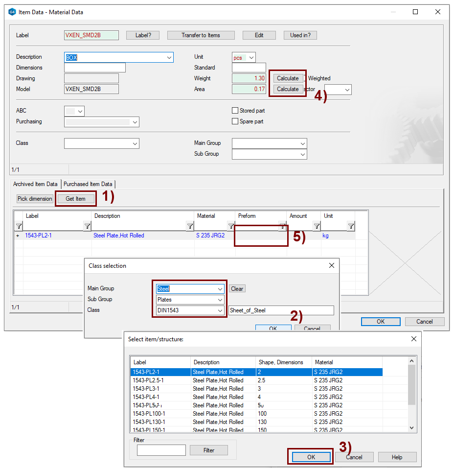
Enter the item data
See detailed instructions for the Modellin parts course exercise 6. Bracket.
-
Right-click function: Item Data. In the figure 1).
-
At the bottom of the dialog: Get Item.
-
The Class selection menu opens.
-
-
Press the preselection button in field Main Group.
-
The Select main group menu opens.
-
-
Select the correct main group.
-
The Select sub group menu opens.
-
-
Select the correct sub group.
-
The Select class menu opens.
-
-
Select the correct class of item.
-
OK perform a search. In the figure 2).
-
The program opens a list of items that meet the search criteria.
-
-
Select a row. (Desired raw material).
-
OK copies the data to the part. In the figure 3).
-
If necessary, calculate the weight and (painting) area. In the figure 4).
-
Clear the Preform field, in which case the program itself calculates the required blank size when the unfold drawing is made for the model. In the figure 5).
-
The blank dimensions are shown in the parts list of the drawing.
-
Save the model
-
File > Save or click


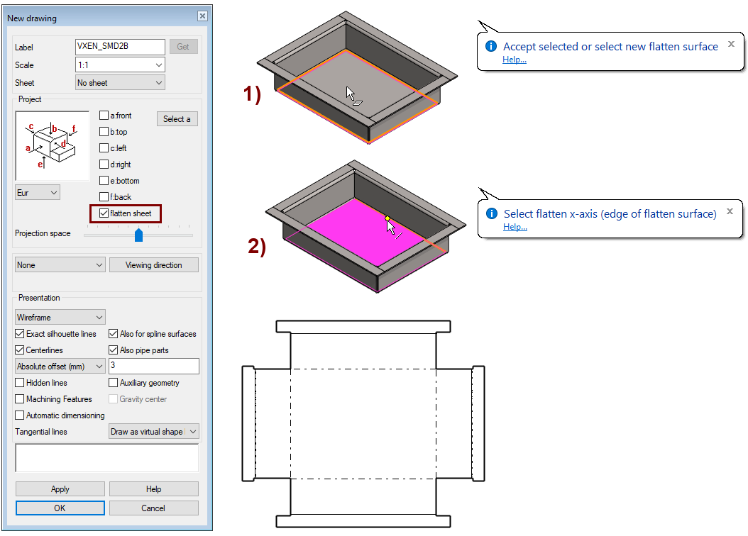
Create an unfold Drawing
When you create a drawing of a model, you can also add an unfold projection to the same drawing.
If you want a drawing in DXF format for a sheet metal machining center, we recommend that you make a Flatten sheet drawing on a 1:1 scale and without a (drawing) Sheet.
-
In the feature tree, click Drawings.
-
Right-click function: New Drawing.
-
Select projections (here only: flatten sheet).
-
Accept selected or select new flatten surfase. In the figure 1).
-
Select flatten X-axis (edge of flannen surface). In the figure 2).
Save the drawing
-
File > Save or click
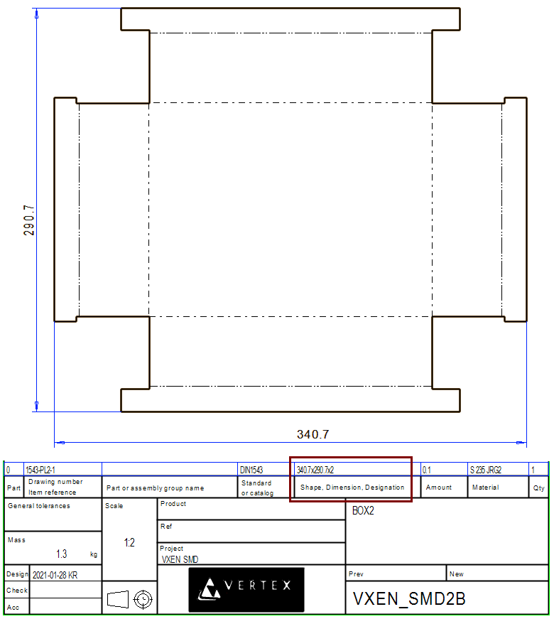
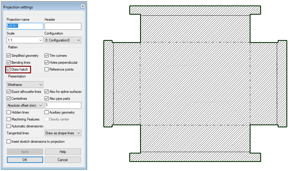
You can adjust the properties of the flattened sheet projection to fit your needs.
Default settings of projection
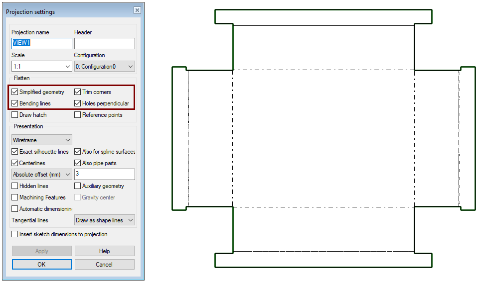
In modeling, notches created in the corners are not removed
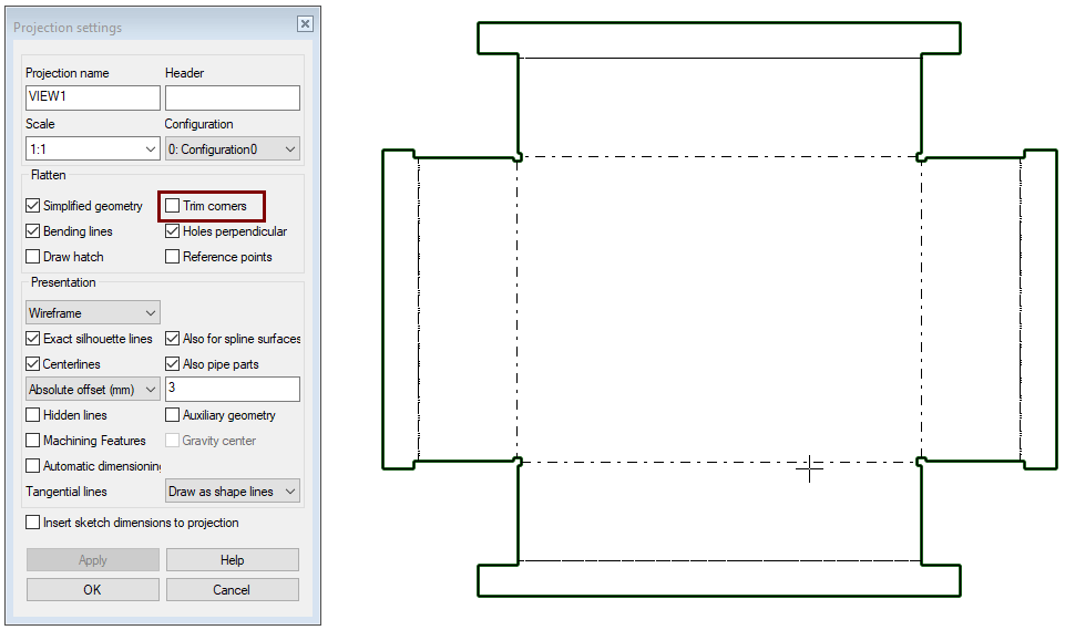
Bending lines are removed
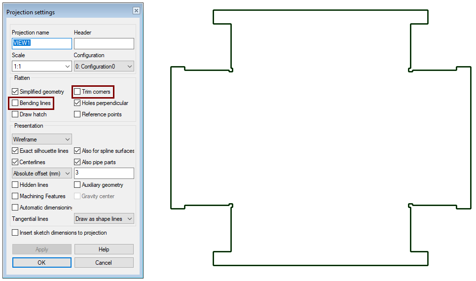
Hatch is drawn
Save the model
-
File > Save or click
Video
Duration 2m 01s
For the best quality for your video, watch it:
-
In full screen mode.
-
With a resolution of 1080pHD.