

Exercise 10: Hood
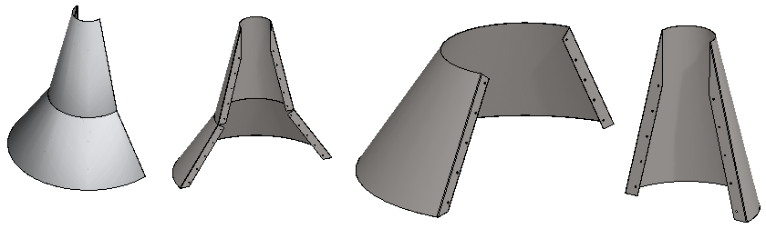
This exercise was carried out with version 27.0 (Vertex 2021).
In this exercise you will learn to
-
To create a jig part by rotating the sketch180°.
-
How to use a jig to model sheet metal parts.
-
Orient a linear feature pattern using geometry.
-
To mirror a feature by auxiliary level.
-
Entering of material information.
-
Create drawings for parts and assembly.
Functions to be used:
-
File > New > Part.
-
New > Part (In the assembly).
-
New Sketch > To vertical (XZ) plane.
-
Operation: Boss > Revolve.
-
Faces > Copy Face > To volume
-
Add Flange.
-
Mirror Feature.
-
Item Data.
-
Drawing > New Drawing.
-
Create a new assembly.
-
Create a new part in the assembly: Jig.
-
Modeling jig.
-
Return to assembly.
-
Create a new part in the assembly: The lower part of the hood.
-
Model the sheet metal with the Face > Copy Fcase > To Volume function, to which you add flanges and mounting holes.
-
Enter the raw material information and create a drawing for the part model.
-
Return to assembly.
-
Create a new part in the assembly: The upper part of the hood.
-
Model the sheet metal with the Face > Copy Fcase > To Volume function, to which you add flanges and mounting holes.
-
Enter the raw material information and create a drawing for the part model.
-
Return to assembly.
-
Create a drawing for the assembly.
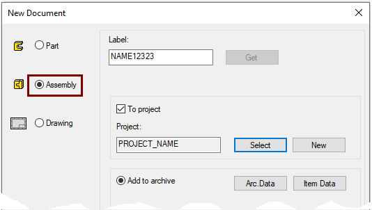
Create a new Assembly
-
File > New > Assembly.
-
Enter the label (which is also the name of the model and by default will be the name of the drawing).
-
Enter the archive information by clicking Arc.Data.
-
Select the project where the model will be saved.
-
OK.
-
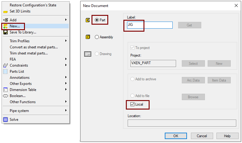
Create a local part
-
Right-click function: New.
-
Click: Part.
-
Enter the label of the part.
-
Select: Local. "Local" means that the part is not made its own file, it is only visible in the assembly.
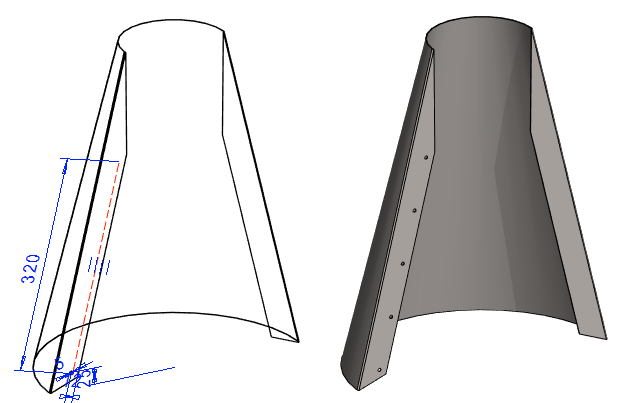
Create the first feature
-
New Sketch > To vertical (XZ) plane.
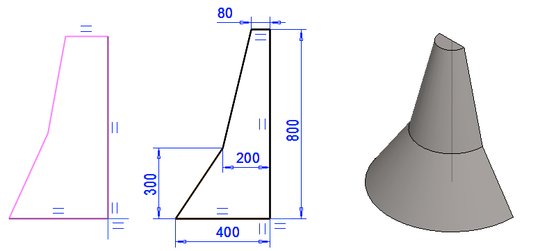
Sketch the shape
-
The function: Polyline.
-
Sketch the shape shown in the image.
-
Start at the origo of the sketch.
-
Note the directional locks.
-
-
Dimension the sketch (The Dimension constraint or the Distance constraint).
-

Operation
-
Boss > Revolve.
-
Length or Angle: 180
-
OK.
-
Click the vertical line, when prompted: Add rotation axis: point at a point or line.
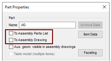
Edit the properties of the JIGI model
-
Right-click function: Properties.
-
Deselect:
-
To Assembly Parts List and
-
To Assembly Drawing.
-
-
OK.
Return from part to the assembly:
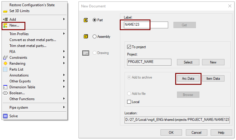
Create a new part in the assembly
-
Right-click function: New > Part.
-
Enter the label (which is also the name of the model and by default will be the name of the drawing).
-
Enter the archive information by clicking Arc.Data.
-
Accept the project, where the model will be saved.
-
OK.
-
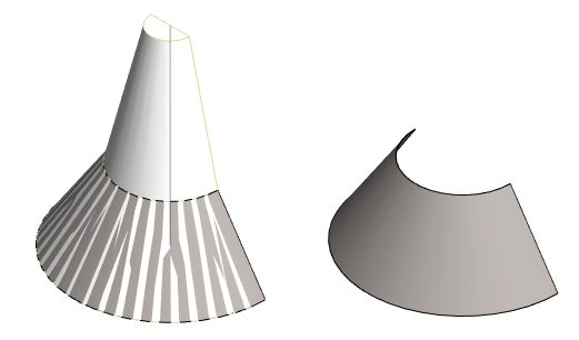
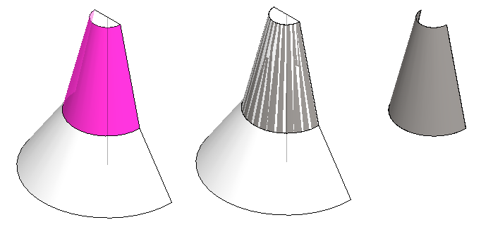
Copy the surface of the jig into a sheet metal part.
-
Right-click function: Faces > Copy Face.
-
Click to the lower conical face of the JIGI.
-
-
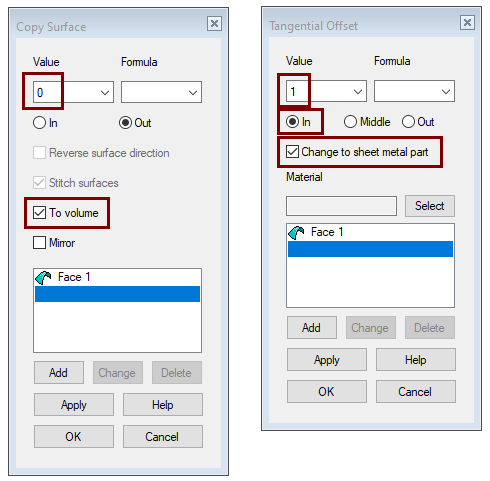
Dialog Copy Surface opens.
-
Leave the value: 0
-
Select: To Volume.
-
OK.
-
-
Dialog Tangential Offset opens.
-
Enter the sheet metal thickness value: 1.
-
Click: In (Part is generated from the surface inwards).
-
Select: Change to sheet metal part.
-
OK.
-
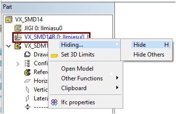
Hide the JIGI
-
Right-click function: Hide Others
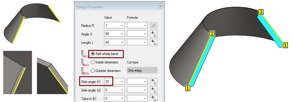
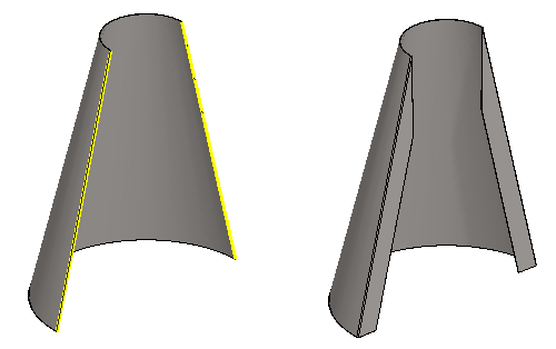
Add flanges for attachment
-
Click two lines from the inside back of the hood.
-
Right-click function: Add Flange.
-
Radius R: 1
-
Angle A: 90
-
Length L: 40
-
Side angle 1: 35.
-
Option: Add whole bend.
-
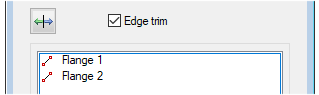
If the program were to interpret the ends of the selected lines so that the end 1 on one side was at the top and the other side was at the bottom, then.
-
Click the first flange (from the dialog box).
-
Accept or enter a new value for Side Angle A1 or A2 and press the Apply button.
-
Click the second flange.
-
Accept or enter a new value for Side Angle A1 or A2 and press the Apply button or OK.
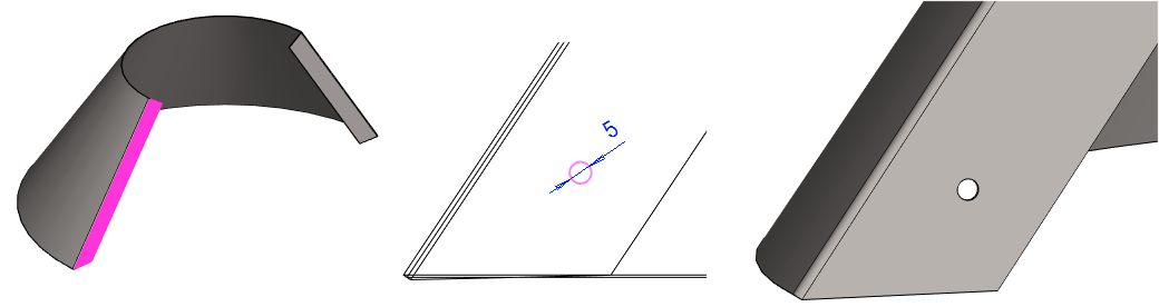
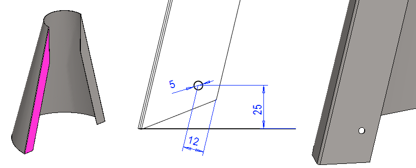
Sketch the mounting hole on the other flange
-
Click on the face shown in the image.
-
Right-click function: New Sketch > Face.
Sketch the shape
-
Sketch a circle.
-
Add the Diameter constraint: 5.
-
Operation
-
Boss - Extrude - To Next Face
Create a pattern of mounting holes
-
Select a feature from the feature tree or hole surface from the model.
-
Right-click function: Feature pattern.
-
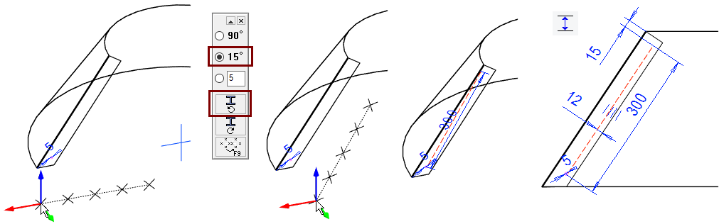
Accept default selection: Linear.
-
Length-direction, Number: 5.
-
Length-direction, Delta: 75.
-
Leave the default values for Width-direction.
-
OK.
-
-
Turn the direction of the pattern to approximately a correct position using the help menu: 15° turn and counterclockwise.
-
To position the pattern, click the cursor in the center of the circle.
-
Add the Distance constraint between the series guide line (red dashed line) and the edge line: 12.
-
Add the Distance constraint between the end of the series guide line and the line at the top of the flange: 15.
-
OK.
Mirror the mounting holes
-
Restore the Lateral (YZ) plane, if it is not already visible.
-
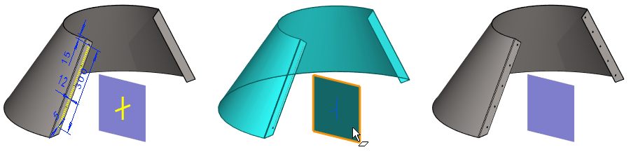
In the feature tree, select the feature that has the pattern.
-
Right-click function: Mirror feature.
-
Click on the mirror plane (middle figure).
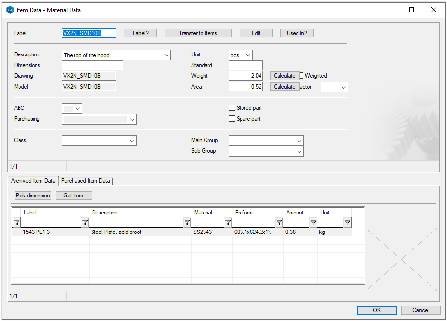
Enter the item data
-
Right-click function: Item Data.
-
See Exercise 2: Box for more detailed instruction.
-
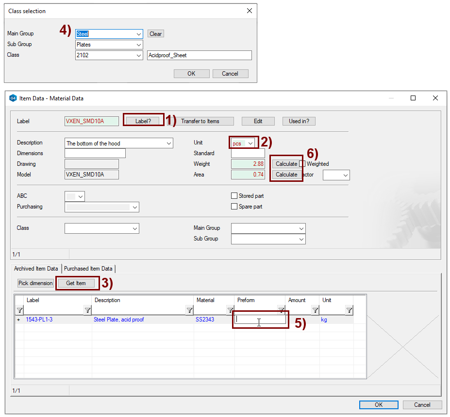
Enter the Label. The Label button adds the item the same ID as the part. In the figure 1).
-
Select the unit. In the figure 2).
-
Search for item information with: Get Item. In the figure 3).
-
Select classes. In the figure 4).
-
OK.
-
Choose Steel Plate, acid proof.
-
Clear the Preform field (so that the program later calculates the length and width dimension for the blank. In the figure 5).
-
You can then calculate the Weight and Area of the sheet. (Note that the area is the so-called painting area, not sheet metal area.)
-
-
OK.
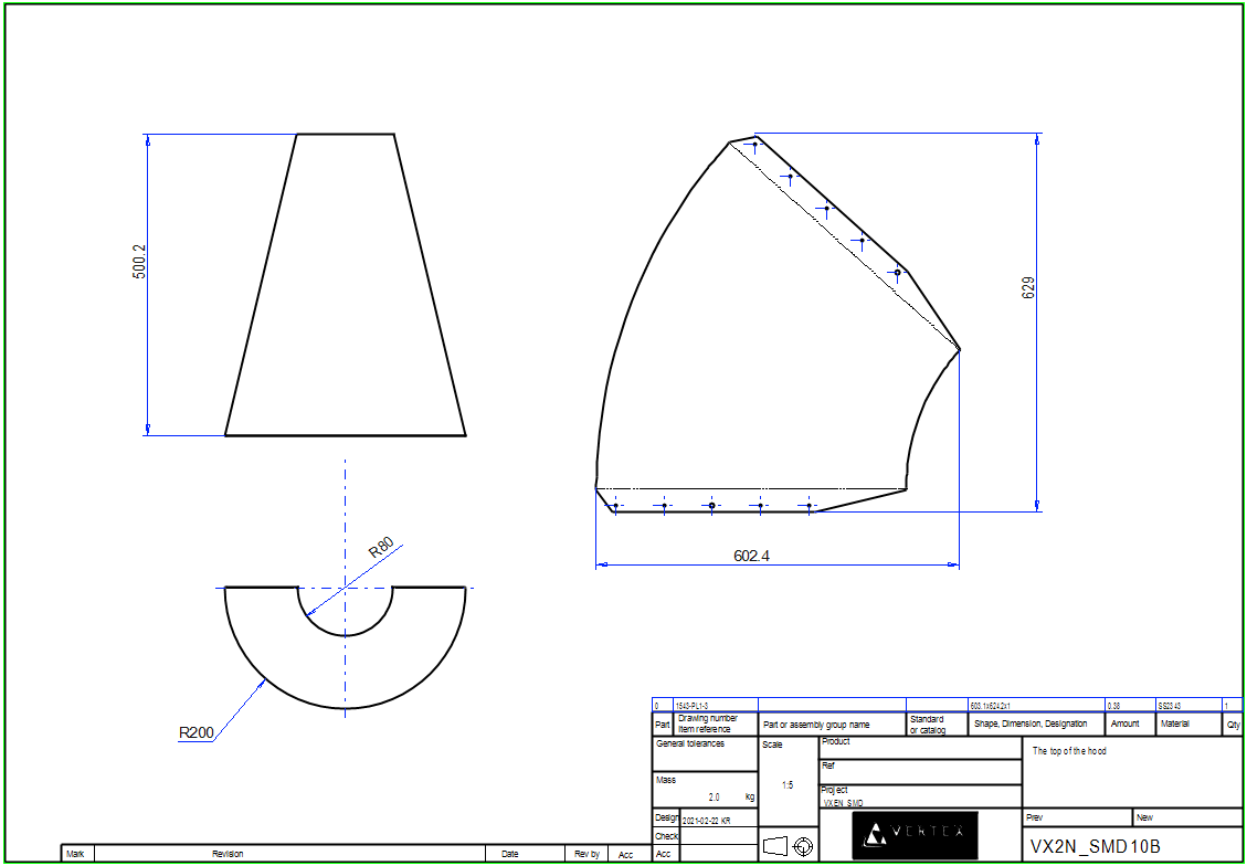
Create a drawing for the part
-
Click the Drawings in the feature tree.
-
Right-click function: New Drawing.
-
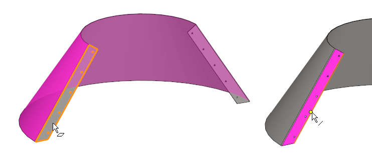
Select projections: Front, top and Flatten sheet.
-
When making a Flatten sheet projection projection, the program suggests the largest surface as the reference surface and stains it red.
-
Replace the surface. Click to the plane of the flange, see figure below left.
-
Accept or click to the reference line pointing in the X direction of the projection, see figure below right.
-
-
OK.
-
Review and accept the archive information.
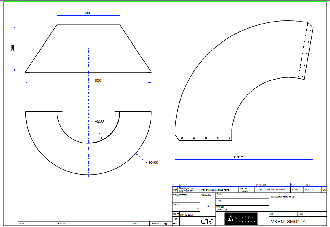
In this case, the blank dimensions calculated by the program (in the field Shape, Dimension Designation in the parts list) are not relevant and are not always calculated correctly with an accuracy of at least 0.1 mm.
Save the dawing
-
File > Save or click


-
Remove the drawing from the desktop.
Return from part to the assembly:
-

Create a new part in the assembly
-
Right-click function: New > Part.
-
Enter the label (which is also the name of the model and by default will be the name of the drawing).
-
Enter the archive information by clicking Arc.Data.
-
Accept the project, where the model will be saved.
-
OK.
-
Hide the lower part of hood
-
Click the upper part that appears in the feature tree.
-
Right-click function: Hiding > Hide.
Copy the surface of the jig into a sheet metal part.
-
Right-click function: Faces > Copy Face.
-
Click to the lower conical face of the JIGI.
-
-
Dialog Copy Surface opens.
-
Leave the value: 0
-
Select: To Volume.
-
OK.
-
-
Dialog Tangential Offset opens.
-
Enter the sheet metal thickness value: 1.
-
Click: In (Part is generated from the surface inwards).
-
Select: Change to sheet metal part.
-
OK.
-
Hide the jig
-
Right-click function: Hide Others
Add flanges for attachment
-
Click two lines from the inside back of the hood.
-
Right-click function: Add Flange.
-
Radius R: 1
-
Angle A: 90
-
Length L: 40
-
Side angle 1: 35.
-
Side angle 2: 76.
-
Option: Add whole bend.
-
Sketch the mounting hole on the other flange
-
Click on the face shown in the image.
-
Right-click function: New Sketch > Face.
Sketch the shape
-
Sketch a circle.
-
Add the Diameter constraint: 5.
-
Add the Distance constraint between the center of the hole and the bottom: 25.
-
Add the Distance constraint between the center of the hole and the edge line: 12.
-
Operation
-
Boss - Extrude - To Next Face
Create a pattern of mounting holes
-
Select a feature from the feature tree or hole surface from the model.
-
Right-click function: Feature pattern.
-
Accept default selection: Linear.
-
Length-direction, Number: 5.
-
Length-direction, Delta: 80.
-
Leave the default values for Width-direction.
-
OK.
-
-
Turn the direction of the pattern to approximately a correct position using the help menu: 15° turn and counterclockwise.
-
To position the pattern, click the cursor in the center of the circle.
-
Add the Parallel constraint between the red guide line and the edge line.
-
OK.
Mirror the mounting holes
-
Restore the Lateral (YZ) plane, if it is not already visible.
-
In the feature tree, select the feature that has the pattern.
-
Right-click function: Mirror feature.
-
Click on the mirror plane.
Enter the item data
-
Right-click function: Item Data.
See the previous part (the bottom of the hood) for more detailed instructions.
Create a drawing for the part
-
Click the Drawings in the feature tree.
-
Right-click function: New Drawing.
-
Select projections: Front, top and Flatten sheet.
See the previous part (the bottom of the hood) for more detailed instructions.
Save the dawing
-
File > Save or click
-
Remove the drawing from the desktop.
Return from part to the assembly:
-
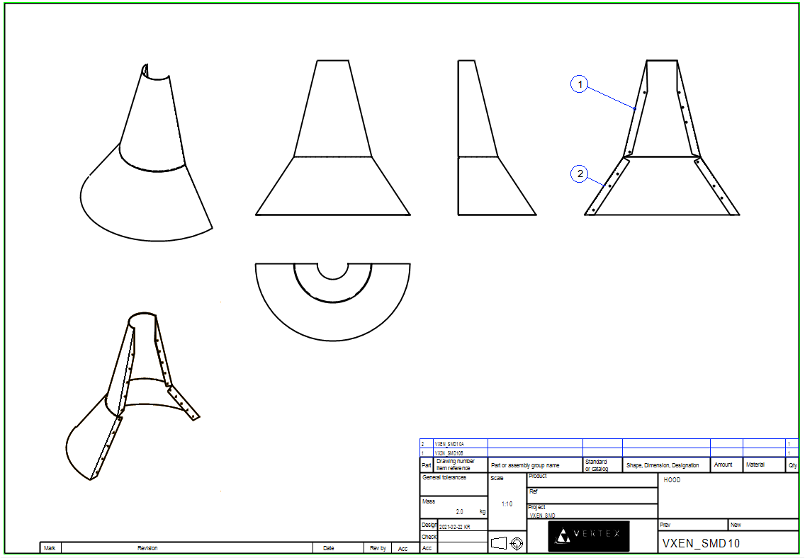
Create a drawing for the assembly model
-
Click the Drawings in the feature tree.
-
Right-click function: New Drawing.
-
Select projections: Front, top, left, back and ISO -45 Front Right.
-
Select Scale: 1:10.
-
-
Add another projectio:
-
Right-click function: Projection.
-
Select: ISO, 45 Back Right.
-
Select: Shading + Wire frame.
-
Save the dawing
-
File > Save or click
-
Remove the drawing from the desktop.
Save the model
-
File > Save or click
Video
Duration 4m 53s
For the best quality for your video, watch it:
-
In full screen mode.
-
With a resolution of 1080pHD.