Basics
G4 and Flow provide excellent features for the design of hydraulic blocks and the generation of production data. The system produces machining data for the machining center from the block design, eliminating the need for work drawings altogether. Thus, we support the increasingly popular MBD (Model Based Definition) philosophy.
To implement the block design feature, the following are required:
-
A license option for block design in the Vertex G4 License.txt file or on the license server.
-
The necessary components and geometries in Vertex Flow.
Modeling Approach
Assembly Start
A hydraulic block is always an assembly model. The first part introduced into the assembly is the part model "BLOCK" from Flow, which serves as the blank for the hydraulic block.
When the model BLOCK is brought in as the first part to an empty assembly in Flow, the program automatically saves the machined block part as a new item and model in Flow, and it also activates the property ‘Block Assembly’ for the assembly. If the first part added is not BLOCK, the program interprets the assembly as a standard assembly.
After this, drilling and other components are added around the block. During the placement of components, the program automatically asks for the distances from the edges of the block. These can be skipped using the Esc key, and distances can also be entered manually.
After adding, moving, or modifying components, it is essential to execute the machining operations using the assembly’s context-sensitive function Machining Features > Execute.
Drilling Components
Drilling components are part models that can be positioned on the side of the block to perform machining operations on the block part. Drilling components are read from Flow as parts into the assembly. Note: since these are machining parts and not "real" parts to be added to the assembly, they are not imported as items and do not have item numbers associated with them in Flow.
Component models are stored in Flow, and the ‘Do Not Update’ checkbox is activated for them on Flow's model card. Examples of drilling components can be found in the G4 component library.
Parts
Parts that are actual items to be added to the assembly, along with features that perform machining on the block, are created in G4 as assembly items. The property ‘Break Down to Parts List’ is checked in G4 for the assembly. Such a sub-assembly will be treated as a local component in the block assembly, but it will update if the model is changed in Flow. If it is desired that the assembly does not update, the ‘Do Not Update’ checkbox is checked on its Flow model card.
Drawings
From the block assembly, at least an assembly drawing and possibly a drawing of the machined block are typically created.
Machining Notations and Machining List
Machining notations and the machining list can be obtained from the "Notations" menu.
Machining Notations
Machining notations and projection dimensions are automatically generated in the projection.
Text Engravings
Texts are added to the surface of the block as sketches, where text is included using the “Add Notation” function. It is advisable to use a "wireframe font," such as NORMAL_OLD. The sketch is saved as a control curve on the surface of the block.
Engravings are printed in the machining list.
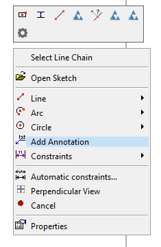
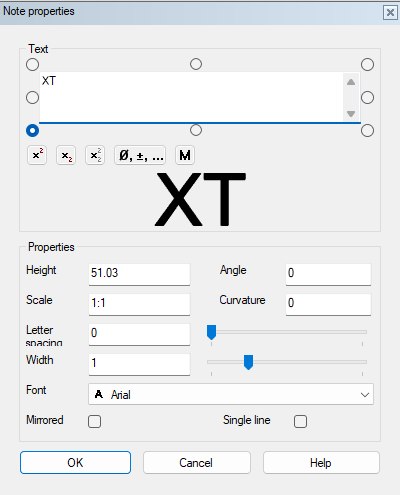
Image: Text added to a sketch, which produces an engraving on the surface of the block.
Part Lists
Drillings are typically models without part number associations. Components that need to be included in the part list must be saved in Flow with an associated part number, and they should be added to the assembly as part numbers.
Machining for Assembly-Specific Linked Components (Parts to be Included in the Part List):
These components are modeled as assemblies that must have the "Explode to Part List" property. Additionally, in Flow, the "Do Not Update" checkbox must be checked. The linked component that is desired for the part list is brought in as a part number, and the machining geometry is also modeled as a local part. A handle is added such that when the component is brought into the block assembly, the z-axis points outward from the surface of the block.
Here, the drilling is a local part that does not appear in the part list but performs the machining operation. The part list for the block assembly will include one line from this model, referencing part number V35400.
It is generally advisable to modify the block part and its drawing manually from the block assembly, ensuring that the machining data updates correctly in the block and its drawing. However, in Flow, the block also exists as its own part number, model, and drawing.
The material information for the block (raw material) is selected in the usual manner, either by adding it in Flow or by dragging the material part number to the part in G4's browser in the part editing mode.
Implementation
For block design to function correctly, three types of models must be saved in the system:
-
Block blank
-
Drilling components
-
Part-numbered components to be included in the part list.
Block Blank
A part model named "BLOCK" must be saved in Flow.
-
This part should not be assigned any part number.
-
The model file named BLOCK can be found in the Vertex G4 component library under the Block Design folder, making it easy to save to Flow.
If you cannot find a model named BLOCK in Flow, proceed as follows:
(1) Log out of Flow.
(2) Select the Open function.
(3) Enter BLOCK in the quick search field.
-
Vertex G4 will list the models that match the search criteria.
(4) Load the model onto the Vertex G4 desktop by double-clicking the BLOCK model in the browser.
(5) Log back into Flow.
(6) Select the File > Save As function.
-
Vertex G4 will ask: "Should a part number be created for the document?"
(7) Respond with No.
(8) Enter the identifier as BLOCK and select OK.
(9) Restore the model to Flow by selecting File > Restore.
-
Vertex G4 will open the Restore to Flow dialog.
(10) Confirm the restoration by selecting OK.
Component Creation
Component Types
Components are models in Flow that can be controlled by a measurement table if necessary.
Components can either be drilling features or parts that are attached to the block, such as valves. All components can have machining features; for example, a valve creates fastening holes in the block. Additionally, the entire component can be a machining part, meaning it will not appear as a part in the bill of materials (e.g., drillings).
You can easily search for components in the G4 workspace using Windows File Explorer in the folder ...\system\components\Lohkosuunnittelu\Poraukset or ...\system\components\Lohkosuunnittelu\Sun.
Examples
Example Component Drilling1:
In an empty part model, four sketches have been made on the YZ plane (vertical plane), which have been rotated 360 degrees.
The sketches contain variables D1, L1, D2, L2, D3, L3, D4, and L4, which control the diameters and depths of the drillings.
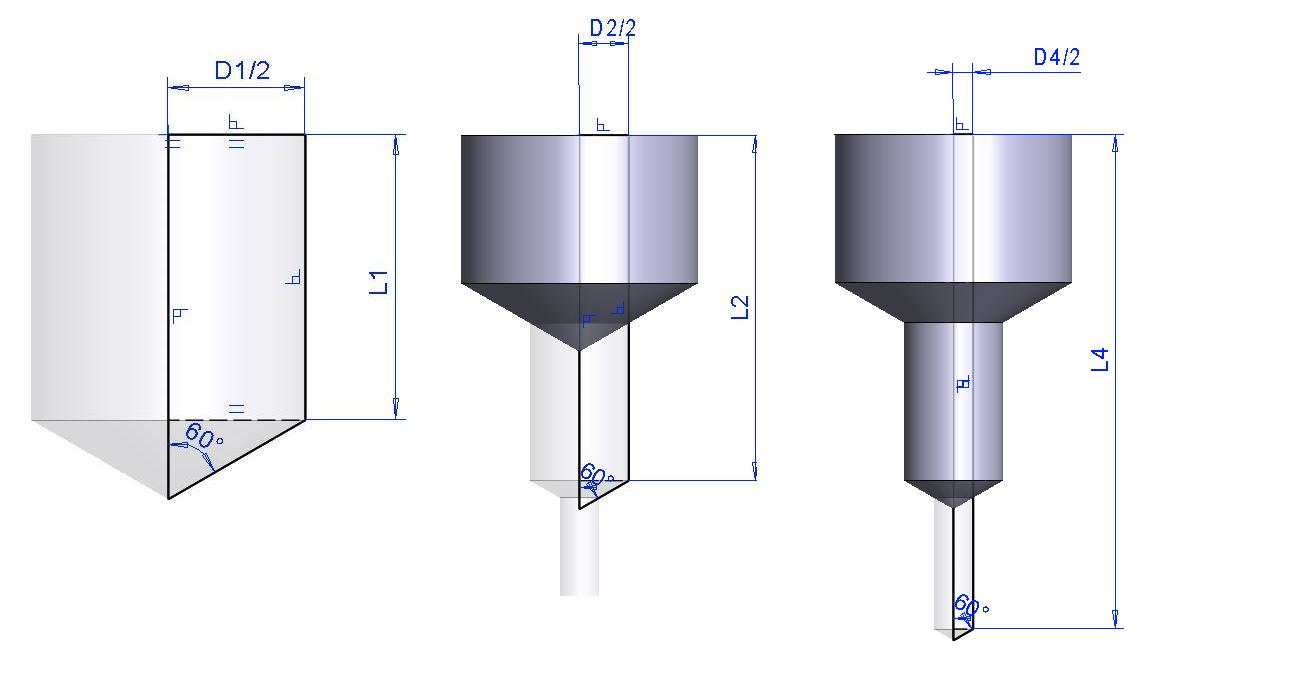
Handles must be added to the components, positioned at the point of the drilling that is desired to be on the surface of the block when the drilling is brought into the block assembly. The blue axis of the handle should point outward from the block surface. The handle will automatically have the property "Only surface search" when the block option is enabled. This facilitates the positioning of drillings as they automatically orient perpendicular to the surface of the block.
Drilling depths always start from the surface of the block.
Typically, the next diameter should always be specified smaller than the previous one, that is, D1 > D2 > D3 > D4. If the next depth is smaller than the previous one, that diameter will not be drilled at all; this allows one component to handle drilling with different diameters at the same point, from 1 to 4 different depths.
Based on this information, when the drilling is brought into the block assembly and a drawing is made after the machining, the correct information is obtained for both the drawing and the machining list.
Example Component Rthread.vxm:
Like the above model, it has 4 sketches with variables D1, L1, etc.
Then a thread symbol is added with variables RD and RL to the surface where the thread is desired. A sketch is then made on the YZ plane so that the specified surface is divided at the lower edge of the thread (variable RL). This is done to allow the thread area to be shaded with a prohibited color (e.g., red 224, defined in the settings).
When checking the machining in the block assembly, the program warns if any drilling intersects a surface colored with the prohibited color.
Note the #CODE# field at the beginning of the Description field, where the line identifier from the measuring table is placed when the component is brought into the assembly, which then automatically appears in the drawing of the block.
The machining features of components can be toggled on and off in the assembly using the M key. This function can also be found in the View dropdown menu.
Machining Data
In the component's identification information, the line:
#CODE!R1"#|Ø#D1!30.5#/#L1!26#|Ø#D2!30#/#L2!30#|Ø#D3!2#/#L3!2#|Ø#D4!1#/#L4!1#
produces the following annotations in the drawing:
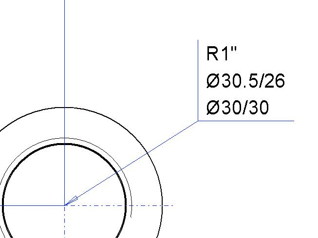
Since the measuring table does not have a default value, CODE does not produce anything in the drawing. The vertical line creates a line break. Drillings that cannot be performed will also not appear in the drawing.
Other Settings
In block design, colors can be used to indicate, for example, areas that should not be machined or to differentiate between pressure and tank lines. The following settings can be defined (setting name):
-
The color number for the area where machining is prohibited. The keyword is restrictedcolorinblock. This can be found in the G4 settings under the "3D" folder. If a color is not defined, all surfaces can be machined. The color is defined for the surfaces of components in areas where further machining is not allowed.
-
Selection of the color for the machining feature. The keyword is setcolorinmeastable. This can also be found in the G4 settings under the "3D" folder. By default, all machining operations are red, but by selecting different colors, it is possible to better distinguish between channels drilled for various purposes.
(1) Select the action File > System Settings > Edit.
-
Vertex G4 will open the dialog window for System Settings.
(2) Select Administrator View (at the bottom left).
(3) Select the 3D Keyword Group.
(4) Search for or add the keyword and its parameter.
Instructions for Block Design in Vertex G4
You can find additional instructions related to block design in the Vertex G4 help.
(1) Press the F1 key in Vertex G4.
(2) Select the Contents tab.
(3) Choose Additional Options > Block Design.