Automatic dimensions
Dimension for brick areas
New option ALL for VALUE:
LAYER(1)=SID|SID~LAYER=0+|SID~PART=AREA|SID~NAME=COVER|SID~VALUE=ALL
When VALUE=ALL, all min and max points of all valid layers are added to the dimension line.
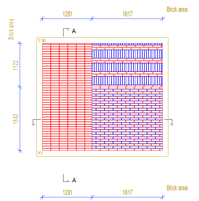
Notice! NAME depends on the brick layer type (the layer in the panel, where the brick tool is). It could be eg. COVER or SIDING
Siding Masonry -> NAME = COVER
Dimension for flashing at panel drawing
'Parameters' field:
COMMON_MACRO_SIZE|SPLIT|MLIB=[LIB]|MCODE=[CODE]|MTYPE=[NUM]
Where:
COMMON_MACRO_SIZE - dimension type (this must always be)
SPLIT - if this parameter exists then dimensions are separate for each macro
MLIB - specifies the macro library of wanted macros to receive dimension
MCODE - specifies the macro code of wanted macros to receive dimension
MTYPE - specifies the macro type of wanted macros to receive dimension
MLIB, MCODE and MTYPE are optional. If none are defined then all macros visible in the view will receive a dimension.
MCODE supports wildcards (for example 'TRIM_TOP*')
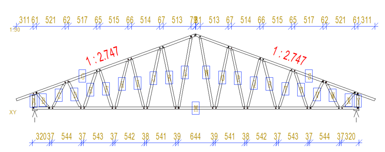
Dimension for truss nodes
Three new truss dimensions have been added to the panel view dimensions library that were previously unavailable to the user. These are
TRUSS=NODES|BOTC - dimension the truss bottom chord nodes
TRUSS=NODES|TOPC - dimension the truss bottom chord nodes
TRUSS=NODES|BOTC|TOPC - dimension the truss bottom chord and top chord nodes (typically used for side dimension)
Panel drawings
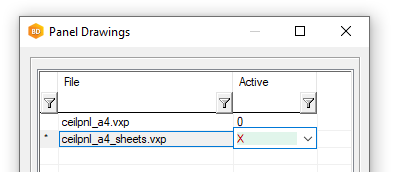
Manage multiple panel drawings per panel
You can now easily manage multiple template panel drawings per panel from the panel template drawing browser instead of going into the component libraries.
Select a template and right-click → properties and you will find Manage additional drawings
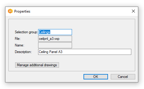
A list will then appear where you can choose X for the extra drawing you want
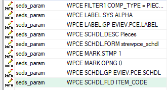
Item codes to schedules
Item codes that have been set for profiles, sheets and building components can now appear in the respective schedule
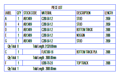
To include the code you must edit the settings for the schedule (Structural Element drawing part lists and the format file to include the field ITEM_CODE)
Part labelling
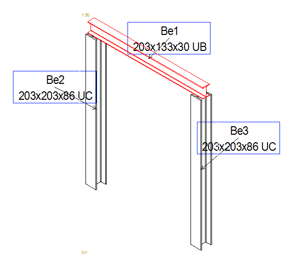
Beam panel labels with leader lines
Beam panel labels with section code
There is a new component library for controlling Panel View labels with examples for piece labels and beam panel labels with leader lines. First untick Items Ids on the first page, on the Draft tab and choose "View label rules" library and "Beam panels with leader lines"
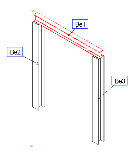
You can customize the beam panel labels to include also the beam cross-section code. The text macro for this is #MAIN_PIECE_CODE# which you can add to the label drawing