
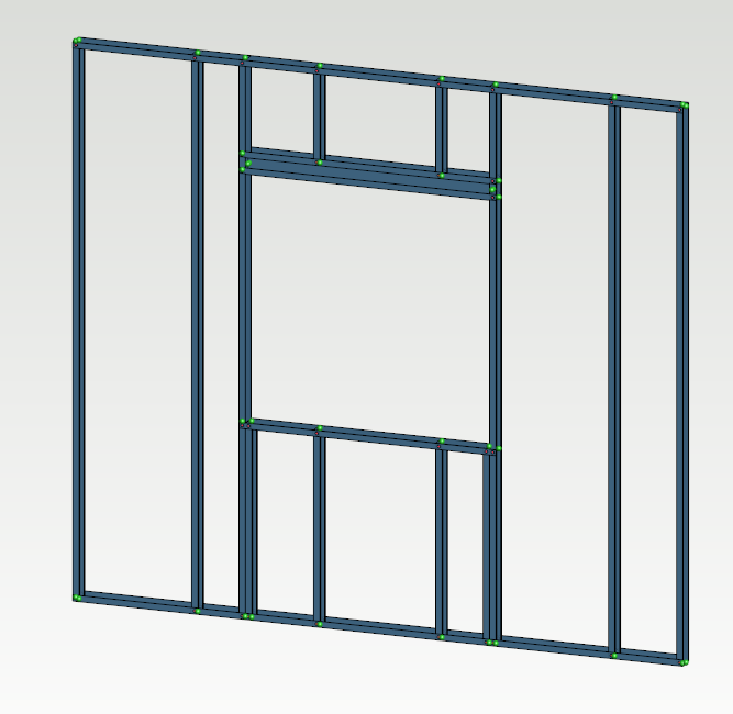
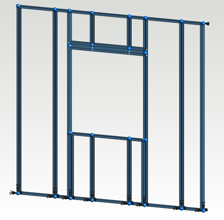
In this example opening header beam is consist of multiple profiles. Beam profiles are connected to carry loads from the opening.
Linking nodes
The opening header beam is built up in four C cross-section profiles and each of them has individual end node. All four members are working in the structure and carry loads. In this example there are two different master-slave links what have to be done, the end of the header beam and the bottom of the cripple member. The same kind of links are created for both header beam ends and the ends of the both cripple members.
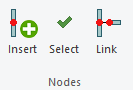
New nodes are added using Insert nodes function.
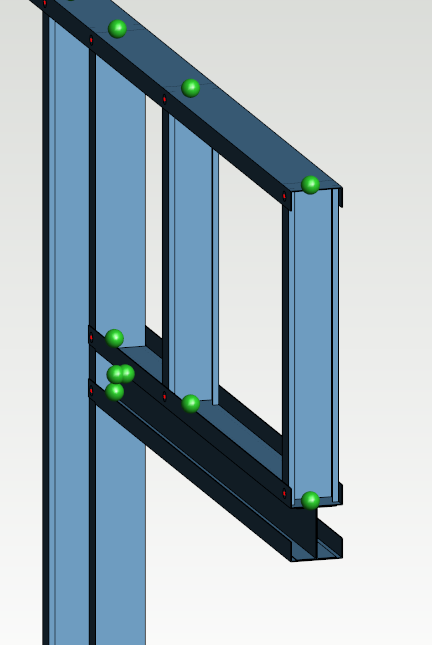
The new added jack stud node works as the master node, so it will be selected first when the nodes are linked. The other four nodes are selected after the master node. The end node of the cripple is working as the master and it need to be selected first as well.
The opening header beam consists of four profiles and each of them has start and end nodes.
Use Link function to link all five nodes.

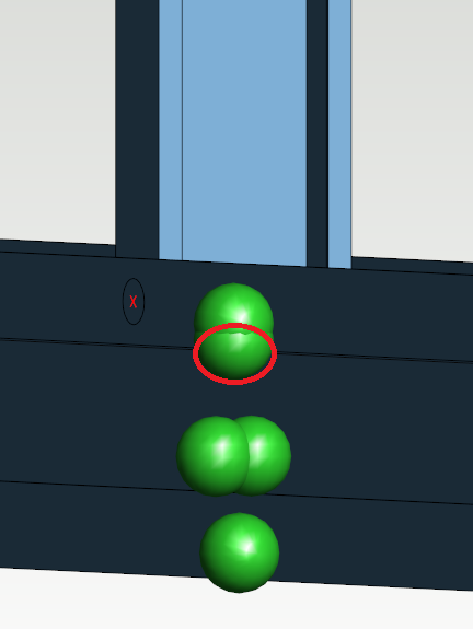
The added jack stud node and the four end nodes.
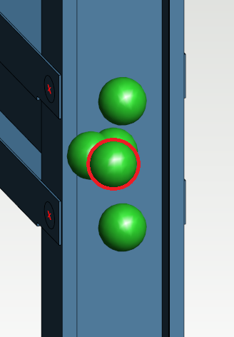
There are only one node in the end of the cripple. In this example four nodes for the header beam profiles are added. The end node of the cripple is marked.
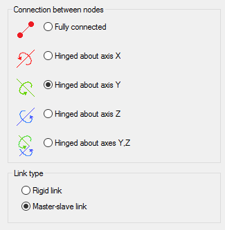
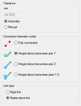
Select hinged about axis Y for all master-slave links.
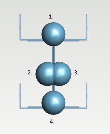
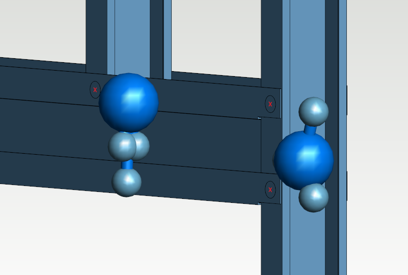
The result for both master-slave links.
Automatic links
Create connections between the other members after the opening header links. Select first one member and use Ctrl+A to select other same kind of objects. Use Link function.

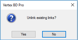
Tolerance between nodes can be set automatically or manually. Do not unlink the existing links.
Set supports
Select all master nodes in the bottom track and set support translations and rotations.
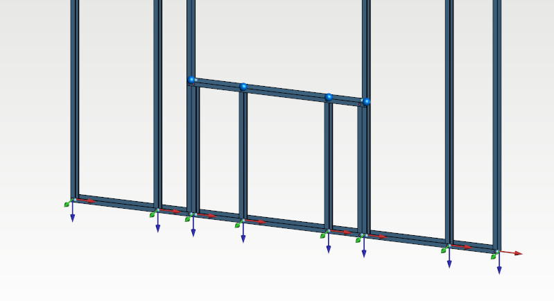
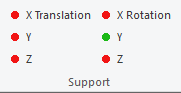
Add a support translation against axis X in the top corner.
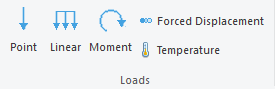
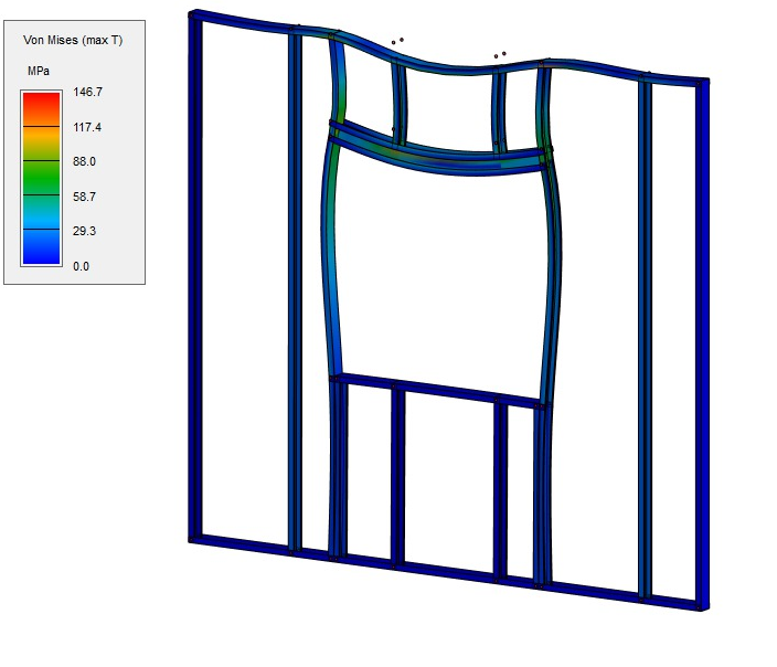
Add loads
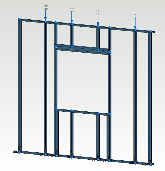
Solve
Use solve function to check how the structure is working. Displacement shows how to structure is behaving under the load.
Capacity Check
Check the capacity of the structure by creating load patterns, setting buckling lengths for the members and running the capacity check.