Labels for panel parts are created when you create panel drawings. The label content and format is defined in system settings.
It is possible to set a specific label for panel parts (profiles) that are of a certain standard cross section, length and material. This can be achieved in the following way:
-
Add the standard parts to a model file that is saved in ../custom/picts folder.
-
Set the desired labels for the standard parts.
-
Edit the panel part schedule settings in system settings.
-
Create the panel drawings.
Create the model file for standard parts
Copy the parts you need and the parts to which those profiles are connected (top plate, lintel etc.) to a separate 3D window.
Select the parts in the framing model and then select Advanced > Copy to a New Window from the right-click menu.
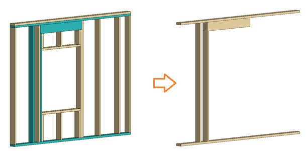
Remove the plates and lintels by selecting Modeling | Tools > Delete object but keep shaping.
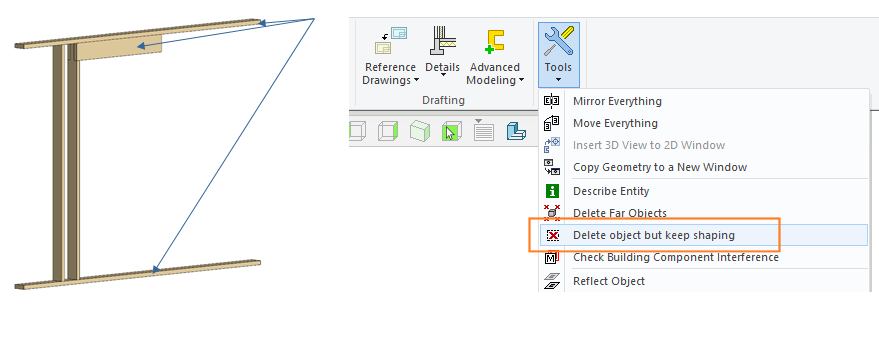
This way the profiles are removed but the features are kept.
Another way is to add standard features such as notches manually to selected locations. However, the method shown above is easier.
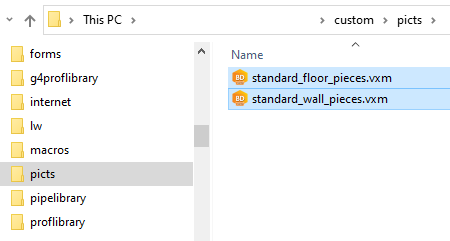
Save the model file to ../custom/picts folder.
For example, a model file for standard wall panel and floor panel pieces:
-
standard_floor_pieces.vxm
-
standard_wall_pieces.vxm
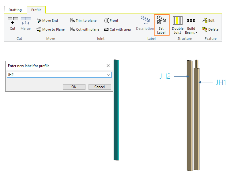
Set the desired labels for the panel parts
Select the part in the separate model window and then select Profile | Label | Set Label. Enter the label in a text box.
Save the model file.
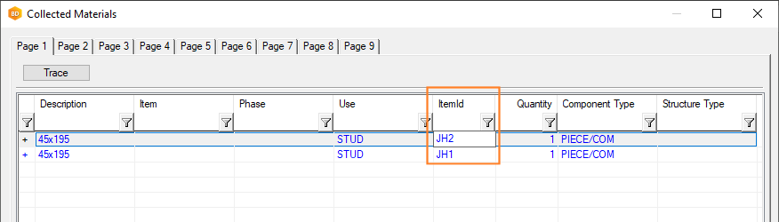
You can check the labels set for profiles by collecting materials from the parts. Select the parts and then select Advanced > Collect Materials from the right-click menu.
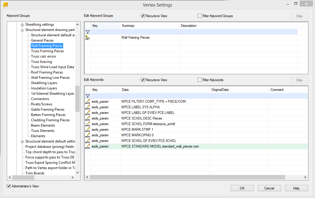
Edit the panel part schedule settings
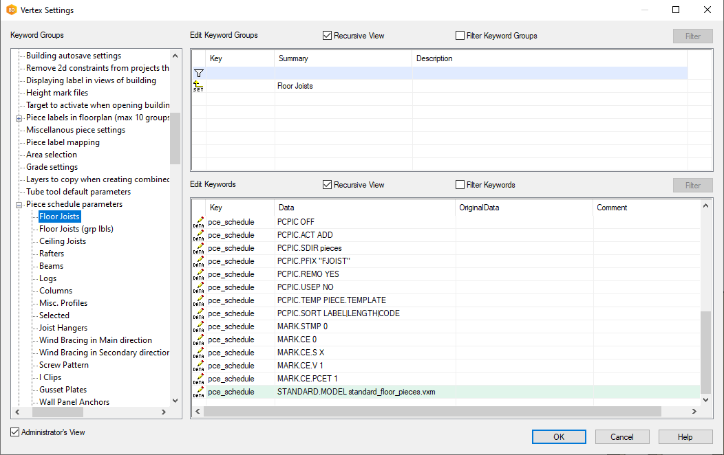
Edit the panel part schedule sets in system settings.
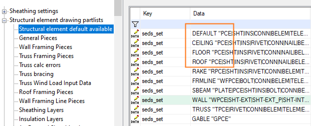
Select File > Preferences > Edit. Select the Administrator's View, and open the branch bdsxx/Structural element drawing partlists.
For wall panel parts, select the group Wall Framing Pieces. Add a new keyword to the group.
-
Key: seds_param
-
Data: WPCE STANDARD.MODEL file_name
For floor panel parts, add the new keyword to the group General Pieces:
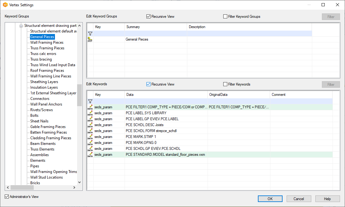
The general PCE set may be used in several sets, for example CEILING, FLOOR, ROOF. The setting will affect all these sets.
Restart Vertex after editing the settings.
Create the panel drawings
The parts that
-
meet the condition specified in the FILTER and
-
have the same cross section, length and material as the parts in the standard_wall_pieces.vxm or standard_floor_pieces.vxm model file
will have the standard label:
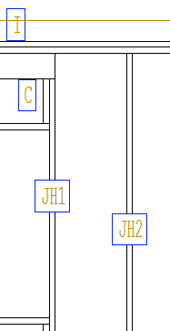
Parts in framing
If you want to use the standard labels also for parts in floor, roof, or ceiling framing area (as opposed to panels), add the definition to the pce_schedule set in question:
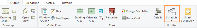
These labels are added with the Output | Profiles | Schedule function.