Several opening trim sets are included as standard in the basic software delivery. These sets usually include:
-
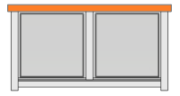
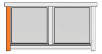
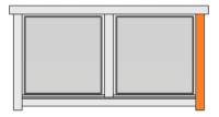
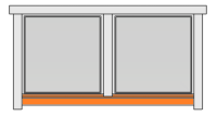
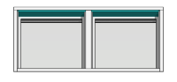
Exterior trims at the top and bottom of the opening and on the sides. There may be more than one part at each side, for example a board and a flashing.
-
Interior trims.
-
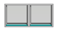
Filling trims. There may be separate exterior and interior filling trims.
If you want to create an opening trim set of your own, you can do it by picking the desired trims from different standard sets into your own set.
The trim parts are G4 models stored in a component library. You can also model your own trim parts and save them to your customer-specific component library.
Opening trim configurations in OPNGTRIM file
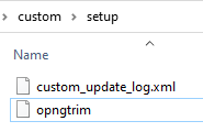
The opening trim sets are defined in the file OPNGTRIM in the system/setup folder. You can copy the file from the system folder to the custom/setup folder. Open the file for editing in Notepad++, for example.
The trim models are stored in a component library, and the name of the component library folder is set at the beginning of the file with the following keyword:
library= OPENING_TRIM
The software supplier's library folder is in the system/complibs folder. The same library is used for all sets unless another library is defined for the set.
The opening trim set definitions start with the following keyword:
set= TYPE NAME
The TYPE can be WINDOW or DOOR. The trim sets for doors are at the beginning of the file, and for windows at the end.
NAME is the name of the set that is shown in the user interface when you select the trim set to be added.
Add your own set to the OPNGTRIM file
You can add your own set definitions to the OPNGTRIM file. For example, you can first add a heading:
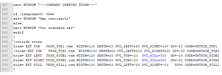
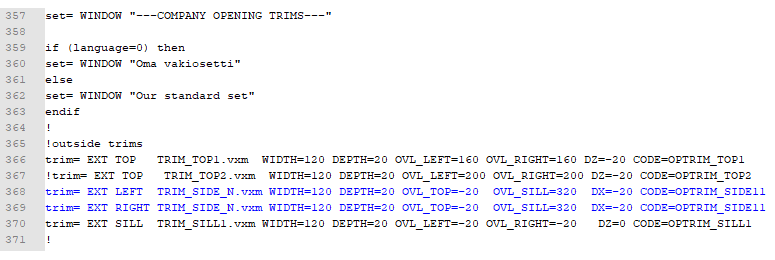
set= WINDOW "---COMPANY WINDOW TRIMS---"
set= WINDOW "Our standard set"
The text in quotation marks is shown in the user interface.
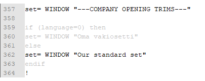
The same OPNGTRIM file is used for program environments in different languages. The set names in different languages are defined with an if-else-endif statement:
if (language= 0) then
set= WINDOW "Oma vakiosetti"
else
set= WINDOW "Our standard set"
endif
The language number for Finnish is 0. The statement above means that if the program environment language is Finnish, the set name is "Oma vakiosetti", and if the language is something else, the set name is "Our standard set".
If you do not need multiple languages, you can leave out the sections greyed out in the figure below.
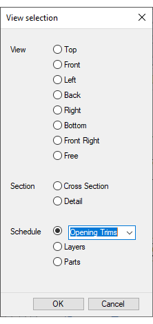
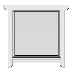
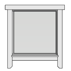
The above definition looks like this in the user interface:
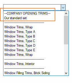
It is still just a heading; you need to add trims to the set as described later.
You can add a separator after your trim set with this heading:
set= WINDOW "----------------------------------------------"
If you want to use a specific trim component library, add the following keyword to the set:
set_library= NAME_OF_LIBRARY_FOLDER
Add trims to the set
You can base your custom trim set on one of the existing sets in the file. Copy the complete set (outside trims, inside trims and filling trims) and then edit the parameters as desired.
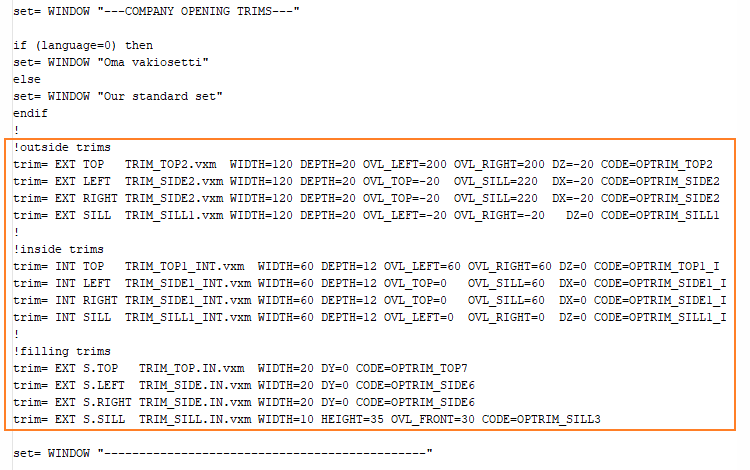
The exterior trim definitions start with the keyword trim= EXT, and the interior trim definitions start with the keyword trim= INT.
You should now test the trim set by adding it to your building:
Edit the trim sets
You can change a trim in the set by copying a trim from another set. For example, you can change the exterior top trim in your set:
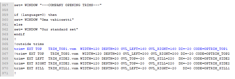
In the figure above, the original trim has been excluded from the set by adding a comment mark (exclamation point) as the first character in the line.
Save the file and test your set by adding the trim set again to the building:
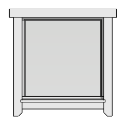
You can furthermore edit the set by changing the trim model files and editing the parameters as desired.
The format of the trim set keyword is the following:
trim= SIDE TYPE MODEL PARAMETERS
|
SIDE |
INT |
Interior side of wall |
|
|
EXT |
Exterior side of wall |
|
TYPE |
TOP |
|
|
|
LEFT |
|
|
|
RIGHT |
|
|
|
SILL |
|
|
|
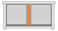
S.TOP |
Separate trims for individual openings in an opening combination. |
|
|
S.SILL |
Separate trims for individual openings in an opening combination. |
|
|
S.DIV |
|
|
MODEL |
*.vxm |
Model file in the component library folder |
|
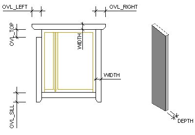
PARAMETERS |
WIDTH |
|
|
|
DEPTH |
|
|
|
OVL_TOP |
|
|
|
OVL_LEFT |
|
|
|
OVL_RIGHT |
|
|
|
OVL_SILL |
|
|
|
DX |
|
|
|
DZ |
|
|
|
CODE |
Same code as in the component library |
The length of the board is based on the width and height of the opening.
For example, you can change the OVL_SILL parameter of the side trims:
Save the file and add the trim set again to the building:
Customer-specific trim models
If you need a whole new trim, you need the model file of the trim, and the trim data needs to be added to the opening trim library.
The software supplier's trim models are in the system/complibs/opening_trim folder. You can copy a model from the system side and paste it to custom/complibs/opening_trim folder. You also need to copy the database files. Rename the model file.
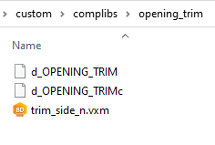
Open the file for editing.
You should take the following things into consideration when modeling opening trims:
-
The origin of the bottom trim must be at the lower left corner of the opening.
-
The origin of the top trim must be at the upper left corner of the opening.
-
The origin of the side trim must be at the bottom right corner of the opening (automatically mirrored when used as the left-side trim).
-
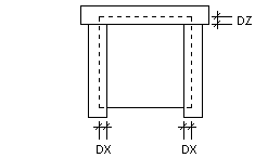
DZ variable can be used to move the board up and down in relation to the opening edge.
-
LENGTH variable is either the width or the height of the opening, depending on the trim type.
-
The end overlap variables for the side trim are OVL_SILL and OVL_TOP, and for the other trims OVL_LEFT and OVL_RIGHT.
-
The width variable of the trim is WIDTH and the depth variable DEPTH.
-
The trim may not move in relation to the origin when the dimensions change.
-
The material category of the trim is TRIM.
In the model file, the variables have values. They can be controlled by entering another value in the OPNGTRIM file.
To add the trim to the library, open the library database for editing. Because the database is now in the custom/complibs/opening_trim folder, the library overwrites the system library.
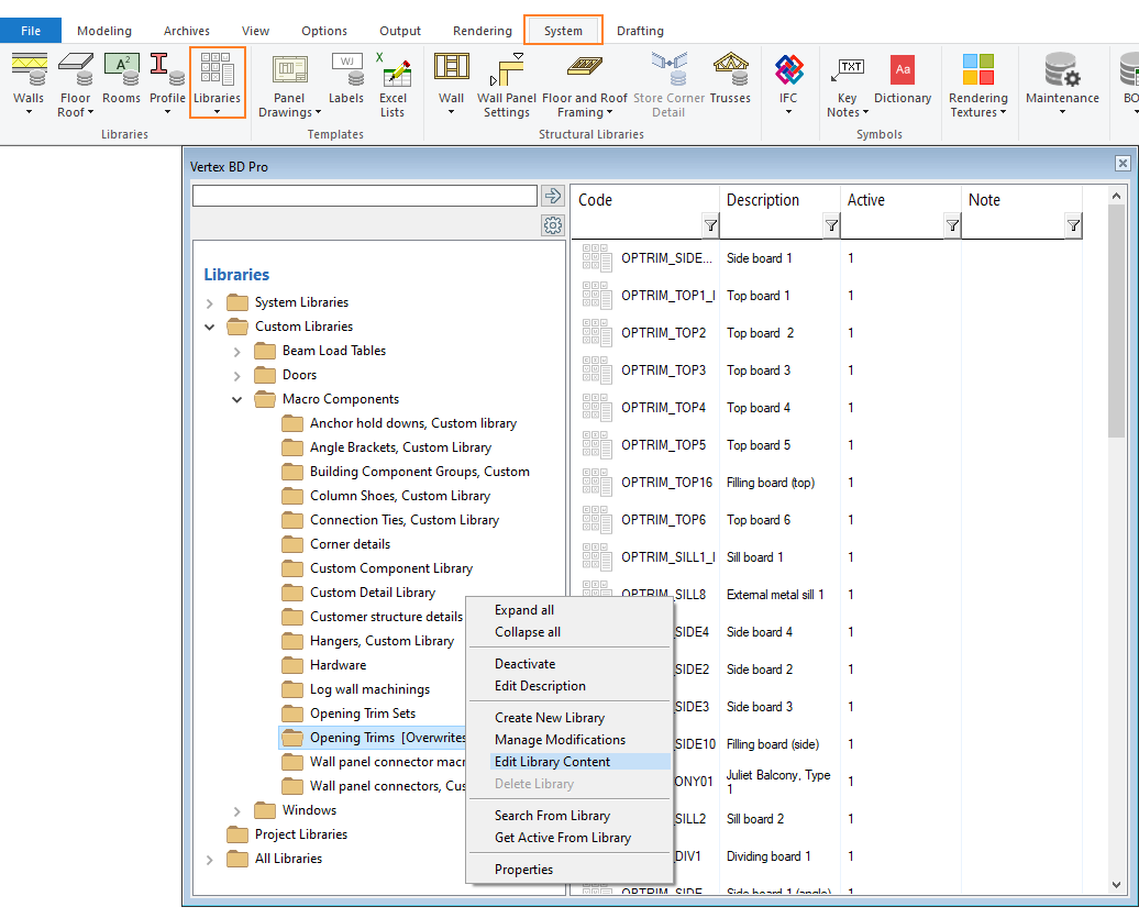
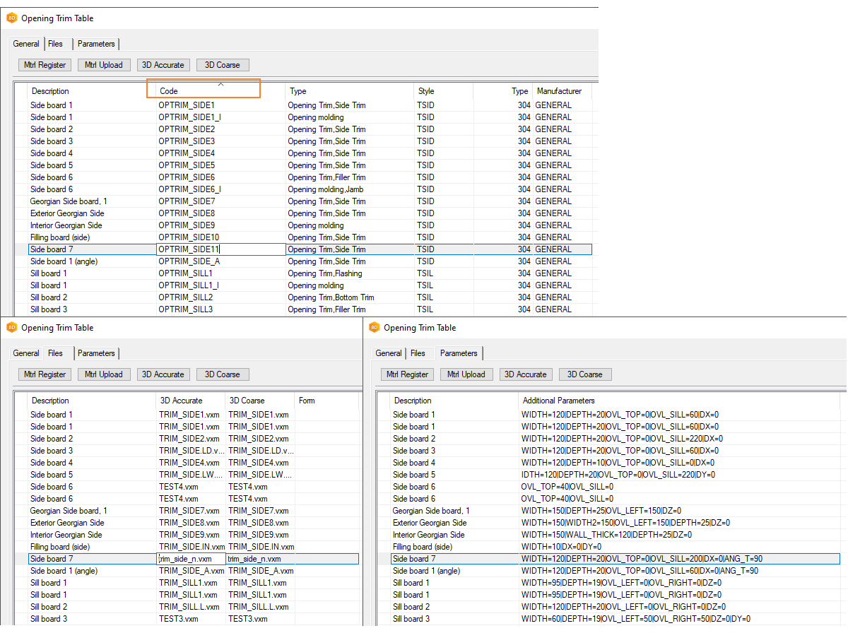
Add the new trim to the database (add or copy row).
-
Note the CODE that is used in OPNGTRIM file. The CODE must be unique for each trim.
-
Select the object type in the first Type field. The type is used to organize the trim parts in the object tree and in Excel reports.
-
Select one of the following as the Style:
-
TDIV - Dividing trim
-
TOTH - Other trim
-
TSID - Side trim
-
TSIL - Sill trim
-
TTOP - Top trim
-
-
Select " 304 Opening Trim" in the second Type field. The other type 306 is used for trims that work as machining tools cutting off the siding material in the building model.
-
Enter the model file name on the Files tab.
-
The dimensions in the Additional parameters field on the Parameters tab are used when you add a single trim.
Click OK to save the opening trim library.
Now you can use the trim in the OPNGTRIM field:
When you save the project, the trims added to the project are saved in the macros folder under the project in the same way as all macro components. After that, the components are read from there, not from the component library. If you make changes to the model files, you will need to remove the folder to update the changes in the model. This is not necessary when editing the OPNGTRIM file.
Cutting trims
A trim can be a cutting trim which works as a machining tool cutting off the siding material in the building model. They can be used for two-layer sidings. The trims are placed in front of the inner siding layer, and they cut the outer siding layer.
The trim model is an assembly model which consists of the trim itself and the cutting shape:
-
Create the trim as an assembly model.
-
Create a part of its own for the cutting shape.
-
When you extrude the sketch defining the shape, select the check box Tool in the extrusion properties.
The program highlights the machining tool in red color. You can show the machining tool in the model by pressing M.
When you add the trim to the opening trim library, select "306 Opening Trim w/ Siding Cutoff" as the Type of the trim.
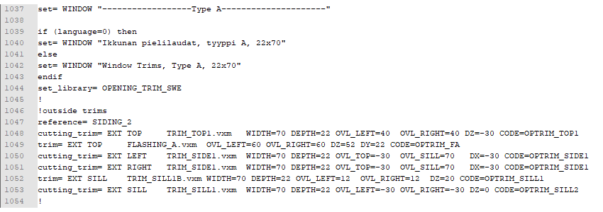
The trim is defined in the OPNGTRIM file with the following keyword:
cutting_trim= SIDE TYPE MODEL PARAMETERS
The siding layer to be cut is defined with the following keyword:
reference= SIDING_2
For example:
Attach the opening trims to wall panels
You can attach the opening trims to wall panels when you generate the wall panel breaks.
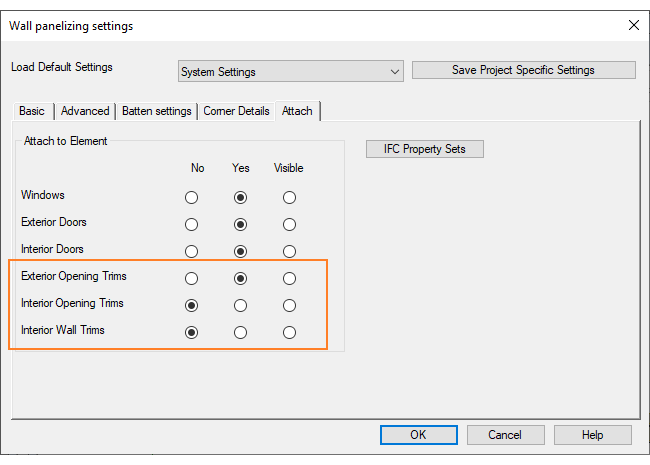
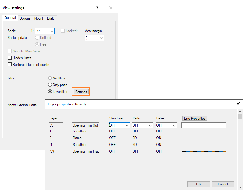
When you select Yes, the trims will be added to the panel drawing view as a layer of their own. The exterior trims are in layer number 99, the interior trims in layer number -99. You can select the method of presentation of the parts from the Parts list.
You can also add a schedule of the opening trims to the panel drawing.