
To be able to add the modeled component to the floor plan drawing as well, you will need a 2D symbol for the component. The program will automatically create it from the model's top projection when you save the component to the component library. If the automatically created 2D symbol is not suitable, you can draw the symbol yourself by using the 2D drawing functions, or you can create a drawing directly from the model, and edit the drawing by removing lines, for example. Set the drawing as the component's 2D symbol by editing the component's parameters in the component library.
Create a drawing
Open the model from the ../custom/complibs/macro_custom folder.
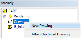
Select Drawings from the model's assembly tree.
Select New Drawing from the right-click menu.
Select the projection data and the scale in the dialog box.
-
Scale - Select 1:1 as the scale.
-
Project - Select the b: top projection. Clear the check box a: front, which is selected by default.
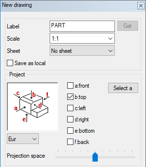
Use the default selections for other properties, and click OK.
Close the Archive Data database view by clicking Cancel and No.
To be able to edit the lines in the drawing, cut the connection between the projection and the model: move the cursor over the projection label in the drawing tree, and select Cut link from the right-click menu.
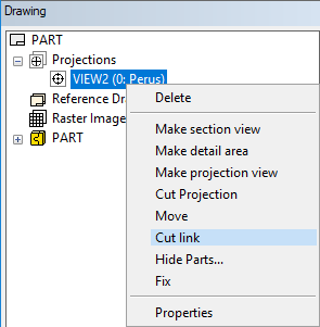
You will be prompted: "Action destroys connection to model. Do you wish to proceed?" Select Yes.
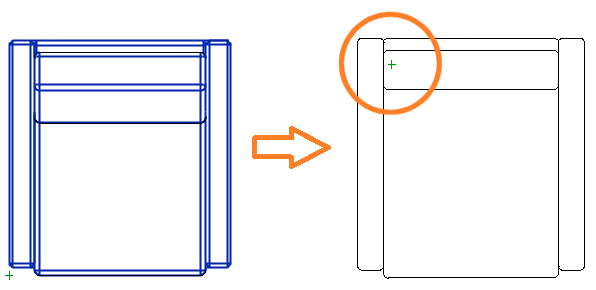
Edit the lines in the drawing:
-
Delete extra lines. Add lines, texts, etc., if necessary.
-
Select a layer for the geometry according to the component type.
-
Edit other properties, for example line width.
-
If you want the 2D symbol to have color fill, add two hatches: a color fill on the layer 59 and a covering hatch on the layer 101.
-
Move the geometry in the drawing so that the drawing origin is in the same location as in the model.
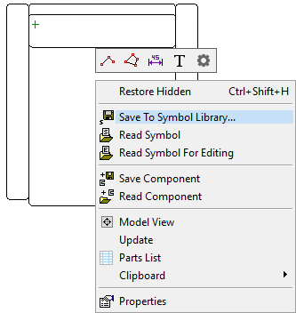
Select Save To Symbol Library from the right-click menu.
Select the component library folder as the saving location (in this example ../custom/complibs/macro_custom), and enter a name for the drawing.
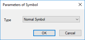
In the Parameters of Symbol dialog box, select Normal Symbol (default).
Close the drawing window. You will be prompted: "Save changes?" Select No. The drawing has already been saved.
Set the drawing as the component's 2D symbol
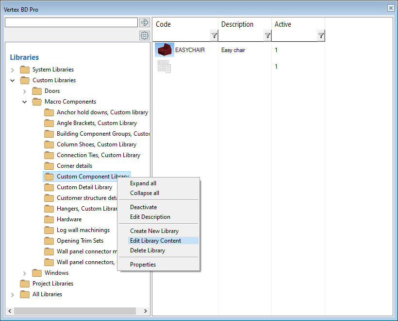
Select System | Libraries | 
Select the folder Custom Libraries / Macro Components.
Select the component library to view the components saved in the library.
Do either of the following:
-
Select the library, and Edit Library Content from the right-click menu.
-
Edit the library data of an individual component by selecting the component, and Properties from the right-click menu.
Move the cursor on the row of the desired component.
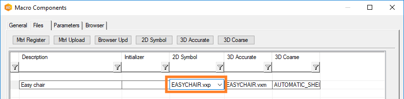
Select the database view tab Files.
Enter the name of the drawing file you just saved to the 2D Symbol field. The file needs to be saved in a folder named after the component library, in this example ../custom/complibs/macro_custom.
Close the database view by clicking OK.