
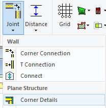
General information about corner details / edge details:
-
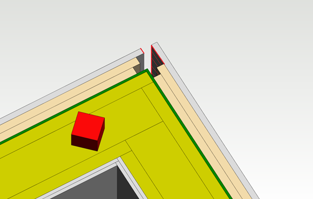
Corner details are used to create connections between layers when panel breaks are added to walls. If necessary, you can manually change the shape of a corner after adding panel breaks, or you can select a desired corner detail from the library. The detail does not affect the positioning of the studs in the corner of the wall main frame layer, but only adjusts the other layers.
-
All the layers that are necessary in the target panel need to be defined in the corner detail. The corner detail can include even more layers, for example pre-defined double sheathings, even though they would not be used. This way, it is not necessary to create new corner details or edit the old ones for every situation.
-
You can add new layers to a corner detail by activating a wall and selecting Properties from the right-click menu. You can add new layers in the same way as for a regular wall structure.
-
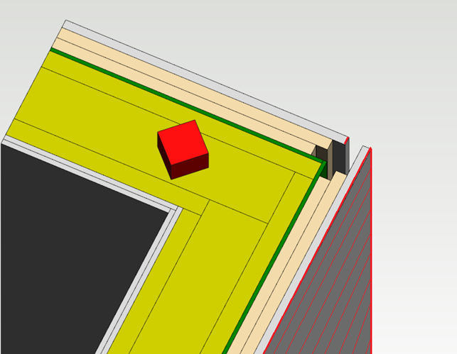
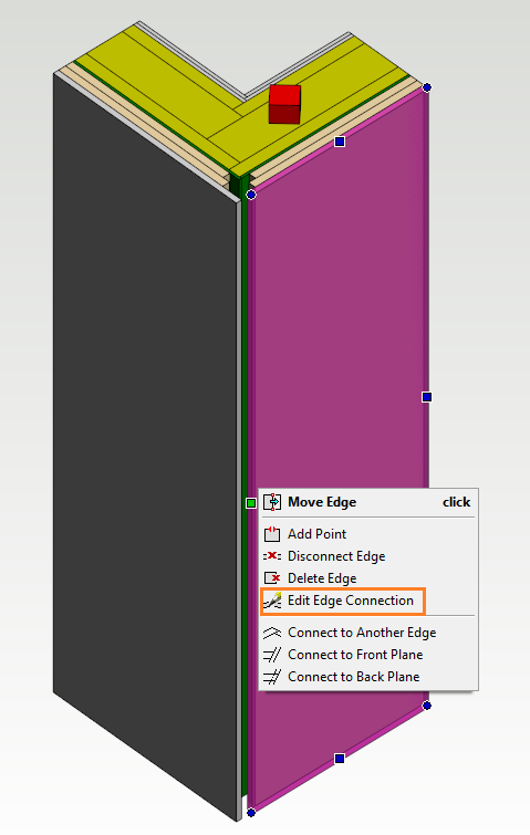
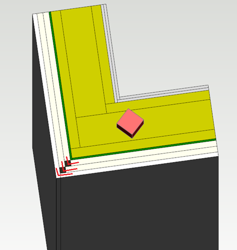
The edges of each layer need to be connected in the corner detail. You can set a mounting gap for the connection and use the gap to adjust the location of the edges even afterwards. You can easily check the functionality of the connection by trying to move the edge from the grip point: if the edge does not move, there is a connection.
-
Connections in a corner detail are layer-specific. For example, the connection of a siding layer is formed between the siding layers of the wall on the left and right side.
-
You can create a connection by using the Connect to Front Plane and Connect to Back Plane. These functions are available in the context-sensitive menu, when you activate a layer (it is highlighted in pink color) and the middle grip point of the edge.

-
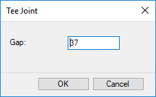
The connection Connect to Front Plane forms a connection between the edge of the active layer and the front surface of the opposite layer. The gap value defines the distance between the edge of the layer and the front surface:
Save a New Corner Detail
-
Open the model file \system\complibs\structdet_sys\strdet_1.vxm for editing. Drag and drop the file to Vertex window.
-
When you edit the corner detail in the system side, the layers of the detail are already connected.
-
Activate the siding layer by clicking the layer twice (the layer turns pink) and open the context-sensitive menu of the middle grip point of the edge. The function Edit Edge Connection in the menu tells you there is an existing connection.
-
You can edit the mounting gap of the connection by using the Edit Edge Connection function. When you change the mounting gap value, the edge of the active layer will move.
-
Edit the edges of all the other layers in the same way. As a result, there are connections between all the layer edges, and the mounting gaps define the locations of the edges.
-
When the edge detail is finished, select System | Structural Libraries | Store Corner Detail →
The program asks you to select the panel and the reference edge → Select the structure → Select the reference edge by clicking the middle grip point → Fill in the detail data in a dialog box:
-
Library - By default, customer-specific details are saved in the custom/complibs/structdet_cst library.
-
Code
-
Description - Displayed in the browser.
-
Browser Path - Folder from which the detail can be selected in the browser. Type the name of the folder in format /folder/ or /folder/subfolder/.
→ Confirm by clicking OK → Close the model window of the detail.
-