You can create a grooved surface on a wall layer by using a 2D pattern drawn in a texture file to model a cladding, for example. The surface of the layer is machined with the pattern in the architectural model. The texture file can be set for an existing structure, or you can set the file for a layer in the wall layer library or in the wall library. You can use the texture files included in the basic software delivery or you can draw the pattern yourself. The texture files of the software supplier are located in system/macros folder:
-
Texture files for wall layers in system/macros/walls folder
You can copy a file from the system folder to the corresponding custom folder and edit it as desired.
-
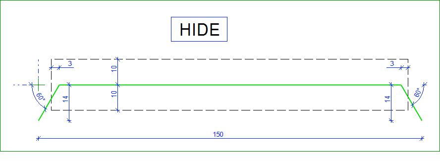
Draw the basic pattern.
-
Set the texture file for a layer.
-
Select the accurate representation for the structure.
-
Edit the texture angle to change the machining direction.
You can set a texture file for a floor, ceiling or roof layer in the same way, see Create a Grooved Floor Surface With a Texture File.
Draw the basic pattern
The program will create a machining polyline by copying the basic pattern one after the other. The polyline may consist of individual lines as long as their endpoints coincide.
Save the drawing file (*.vxp) in the folder custom/macros/walls for wall layers.
For example, patterns for wall layers:
After adding a new texture file to custom/macros folder, you need to restart Vertex BD.
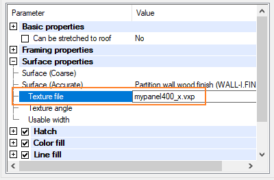
Set the texture file for a layer
Open the wall properties and select the layer.
If all properties are not shown in the lower part of the dialog box, right-click and select Show all parameters.

Open the Surface properties branch and enter the name of the texture file in the Texture file field.
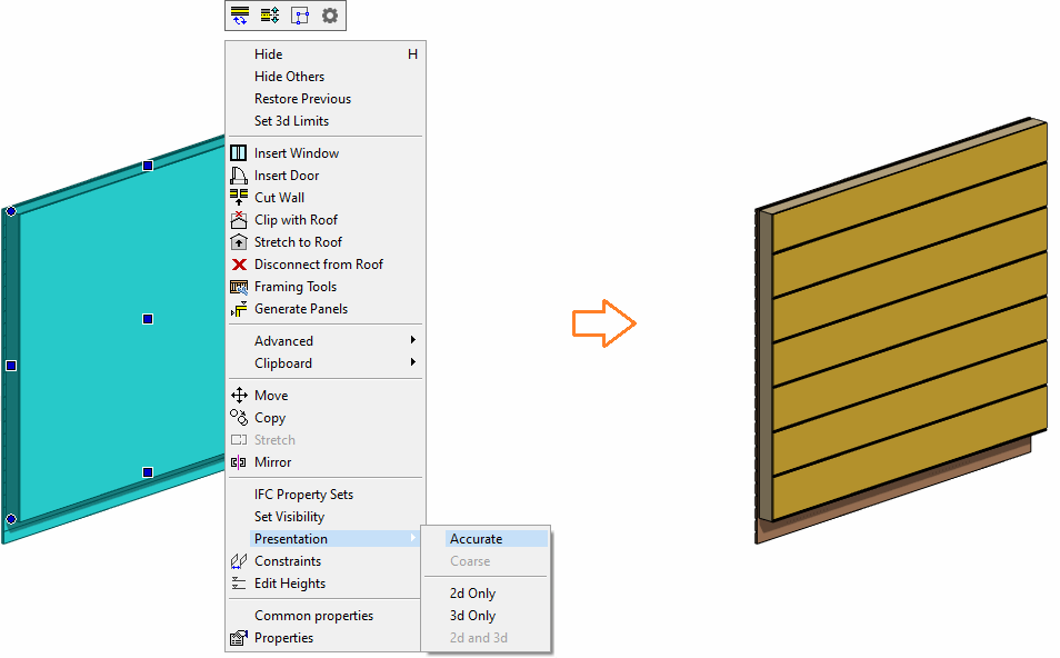
Select the accurate representation for the structure.
Select the wall and then select Presentation > Accurate from the right-click menu.
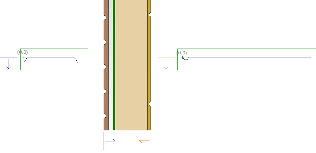
Change the machining direction
You can change the direction of the machining by changing the value of the Texture Angle.
For wall layers:
-
0 - horizontal machining
-
90 - vertical machining
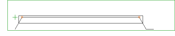
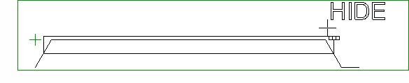
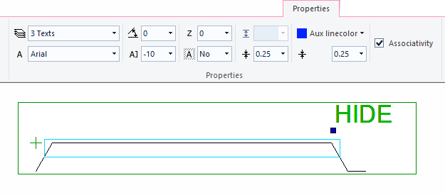
Hide lines from an elevation view
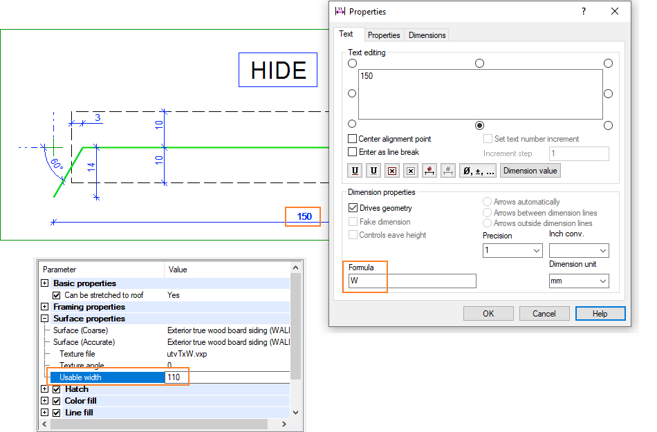
If there are a lot of corner points in the pattern, they may form too many lines in the elevation view. You can hide part of these lines from the elevation view by adding a HIDE box to the pattern drawing:
Draw a rectangle around the points that you want to hide from the elevation view.
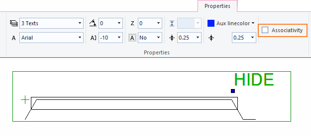
Add the text HIDE to the drawing.
Select the text and click Associativity on the ribbon.
Select the rectangle as the associative element.
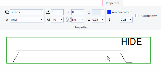
The Associativity becomes checked on the ribbon bar.
Save the drawing.
Parametric texture file
The pattern in the texture file can be controlled with geometric constraints.
It is possible to control the width of the cladding board from the wall layer parameters. When the dimension constraint has the variable W set in the Formula field, the value of the Usable width in the layer parameters is loaded as the value of the dimension constraint. This enables claddings of varying widths by using just one texture file. Solving the constraints requires that 2D Constraint Manager is enabled.