You can create a grooved surface on a floor, ceiling or roof layer by using a 2D pattern drawn in a texture file to model a composite layer, for example. The surface of the layer is machined with the pattern in the architectural model. The texture file can be set for an existing structure, or you can set the file for a layer in the layer library or in the floor, ceiling or roof library. You can use the texture files included in the basic software delivery or you can draw the pattern yourself. The texture files of the software supplier are located in system/macros folder:
-
Texture files for floor, ceiling or roof layers in system/macros/areas folder
You can copy a file from the system folder to the corresponding custom folder and edit it as desired.
-
Draw the basic pattern.
-
Set the texture file for a layer.
-
Select the accurate representation for the structure.
-
Edit the texture angle to change the machining direction.
You can set a texture file for a wall layer in the same way, see Create a Grooved Wall Surface With a Texture File.
Draw the basic pattern
The program will create a machining polyline by copying the basic pattern one after the other. The polyline may consist of individual lines as long as their endpoints coincide.
Save the drawing file (*.vxp) in the folder custom/macros/areas for floor, ceiling and roof layers.
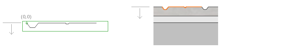
Note the side of the layer to be machined when drawing a pattern for a floor, ceiling or roof layer.
-
Machining to the top layer.
-
Machining to the bottom layer.

After adding a new texture file to custom/macros folder, you need to restart Vertex BD.
Set the texture file for a layer
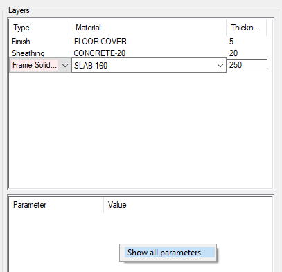
Open the structure properties and select the layer.
If all properties are not shown in the lower part of the dialog box, right-click and select Show all parameters.
Open the Surface properties branch and enter the name of the texture file in the Texture file field.
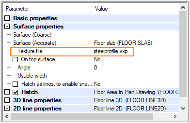
You can use the parameter On top surface to define the surface to be machined.
-
The parameter is selected by default for a top layer in the structure.
-
The parameter is cleared by default for the bottom layer in the structure.
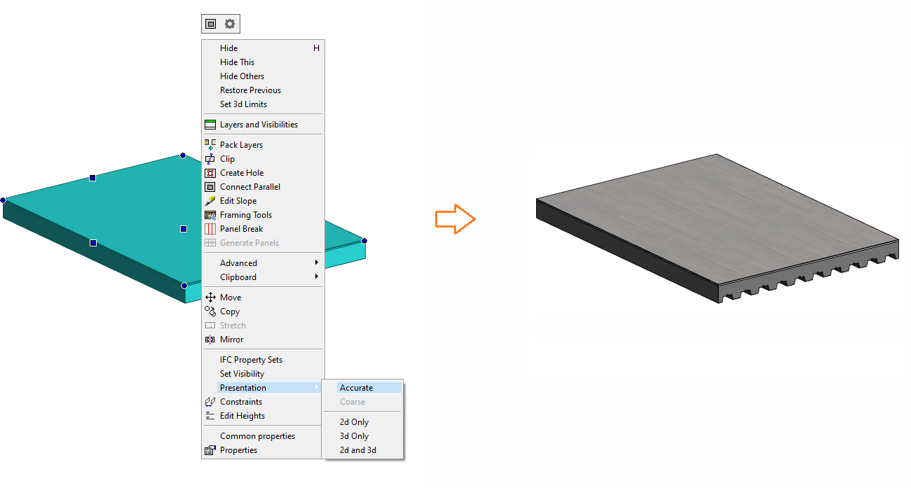
Select the accurate representation for the structure.
Select the structure and then select Presentation > Accurate from the right-click menu.
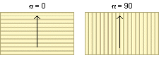
Change the machining direction
You can change the direction of the machining by changing the value of the Angle.
For floor, ceiling and roof layers, the angle is defined in relation to the x axis.
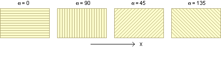
On a slope the angle is defined in relation to the horizontal edge.