
This example shows how to design a simple CFS beam using Vertex FEA functionality. The FEA functionality could be used to design posts and rafters but they are not included in this example.
Check first FEA manual to have further information about the functionality.
Create New Study
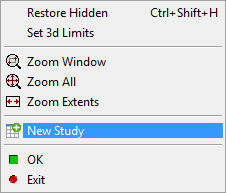
Open the FEA state selecting from contextual menu FEA > 
Select New Study from contextual menu and select the beam profile.
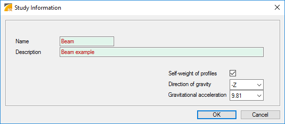
Fill the study information to the dialog.
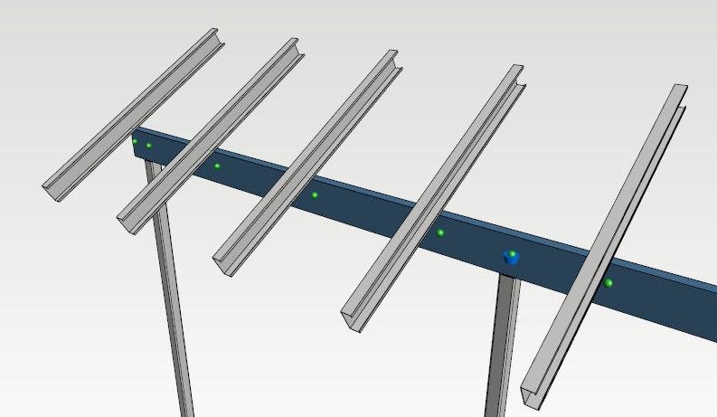
Add Nodes
Loads and supports are connected to the profile nodes. Profile has two nodes in it's both ends when it is selected in the FEA study. New nodes can be added tot he profile if it will be loaded or supported somewhere else than profile's end points.
Select first the beam profile and select Insert nodes in the ribbon menu.
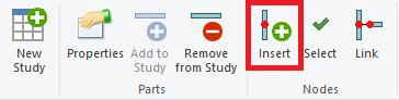
In the insertion mode, node locations can be pointed anywhere from the model and they will be projected to the profile.
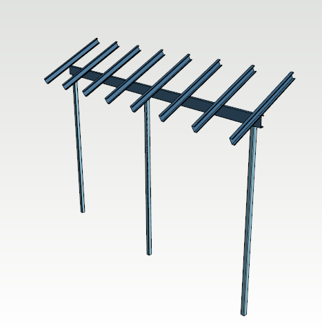
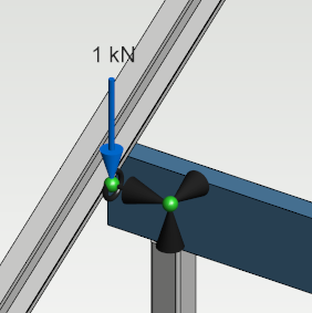
In this example rafters will have some load for the beam and the beam is supported over the posts, nodes are inserted for each rafter and post.
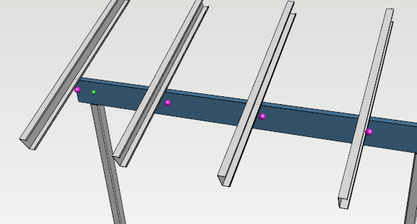
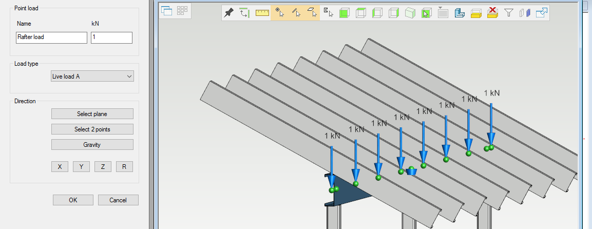
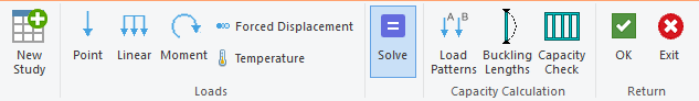
Add Loads
Select Point load in the ribbon menu.
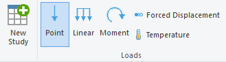
Select all rafter nodes using Ctrl button and confirm pressing V button in keyboard.
Add Supports
Select the first column node and select support conditions in the ribbon menu. Support conditions are defined in six degrees of the freedom, three for translations and three for rotation. Some typical situations are stored in Support Presets.
The first node support conditions.
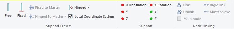
The first node is holding all horizontal loads in the idea case.
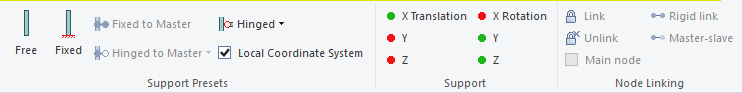
Support conditions for last two nodes.
Restrictions for node freedoms are in 3d model. Black cones are presenting translations and donuts shapes rotations.
Solve Study Stresses
Select Solve study in the ribbon menu.
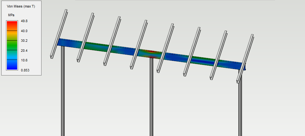
Solver shows different kind of stress plots. Plots can be drawn in colored display or diagram.
Von Mises stress
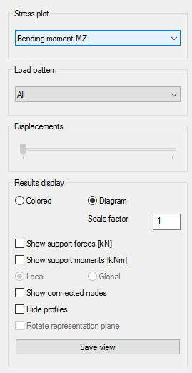
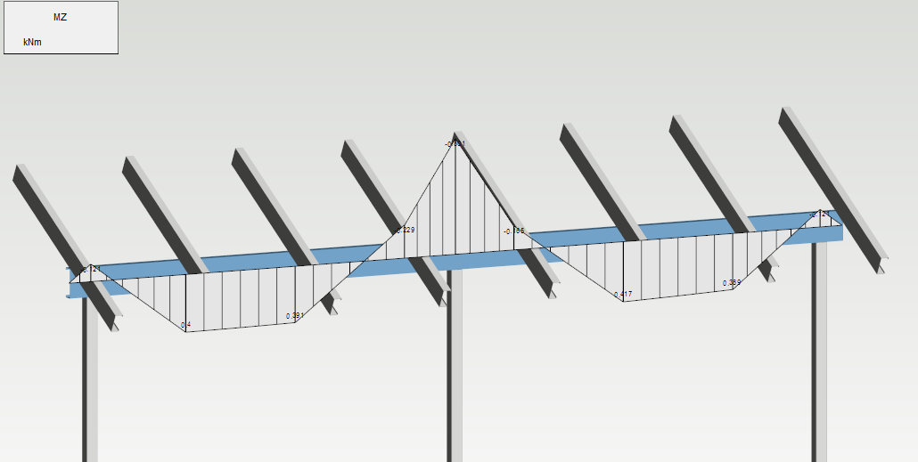
Bending moment
Capacity Check
Check the capacity of the structure by creating load patterns, setting buckling lengths for the members and running the capacity check.