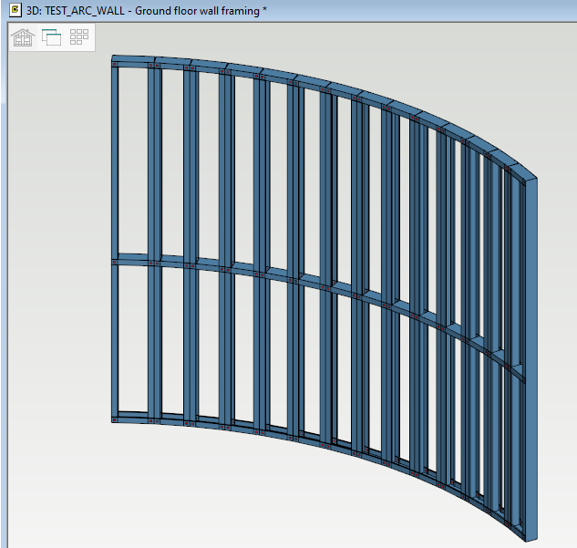
Generally it is a good practice to start designing architectural from bottom upwards and creating framing from top downwards.
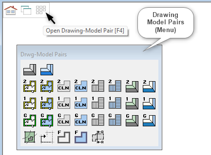
1. Select the Model pair:
-
First we need to change to ground floor drawing model pair.
-
So click on these squares at the top left corner of the Vertex window ( as shown ) to activate the ‘Drawing Model Pairs’ menu.
-
If it hasn't appeared just press ‘F4’ to activate the ‘Drawing Model Pairs’ menu.
-
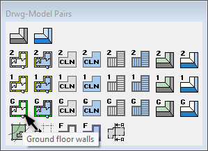
Select on the Ground Floor walls layout as shown
This 


Auxiliary functions may be related to the function you have selected. Auxiliary functions can be found in the context-sensitive menu. Open the menu by right-clicking at the exact point in the working window. You can select several auxiliary functions ( in 2D view ) from the menu. The menu closes when you move the cursor outside the menu. You can reopen the menu by right-clicking.
2. Select Wall Library and wall type:
-
Select an external wall suitable for your conditions and adjust the height and other options such as exterior / interior, C-Section to C-Section or C section to U track. ( Users can choose different libraries according to their own need. )
-
Load Bearing and non-load bearing can be selected by ticking / unticking 'Bearing' checkbox as per the requirement.
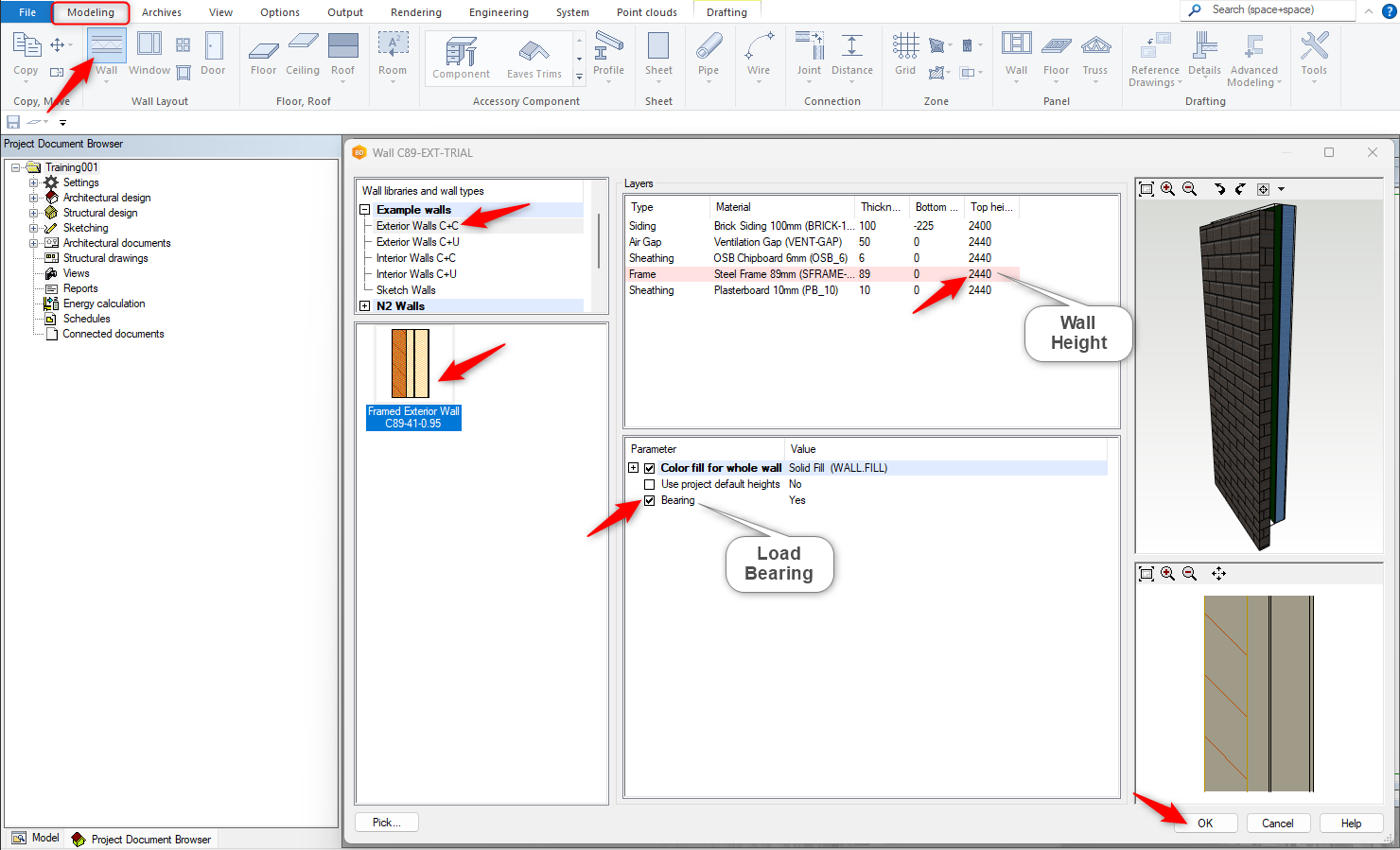
3. Wall Layers adjustment:
-
User can modify wall layers such as brick and ventilation gap thickness by clicking on the number directly and change as per the requirement.
-
Bottom height and top height can be adjusted by clicking on the number directly and change as per the requirement
-
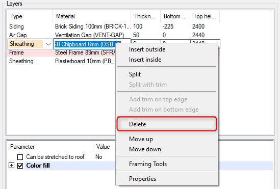
In this scenario, we will delete external Sheeting layers. Click on the layer ( in material column ) first. Right click and form the contextual menu click on delete.
-
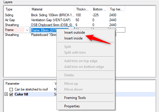
Wall Layers can also be added as well. Depends whether inside or outside of framing wall and then select the Type, Material and thickness from drop down menus as per the requirement and availability of the libraries
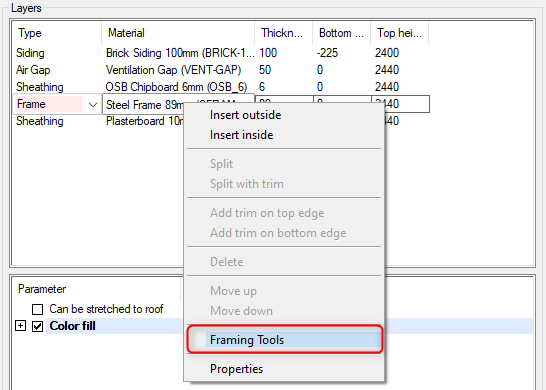
4. Framing Tool
-
The structure parameters of layered wall and horizontal structures are defined for each layer separately using a framing tool. The tool determines the design rules based on which parts (such as studs, rafters and sheets) are added to the layer.
-
The framing tools for the layers of a structure can already be set in the structure library.
-
But you can change the tool during designing and edit its parameters just by right clicking on the material and from the contextual menu select 'Framing Tool'.
-
Always recreate the structure parts when you have edited a tool.
-
Once the settings on all tabs are correct, click on OK.
You can change or edit the framing tool of a wall, floor, ceiling or roof layer by editing the structure properties. Once the panel breaks have been generated, changes made to the wall, floor, ceiling or roof are no longer transferred to the panel. After this, the changes in framing tool need to be made for the panel and its layers.
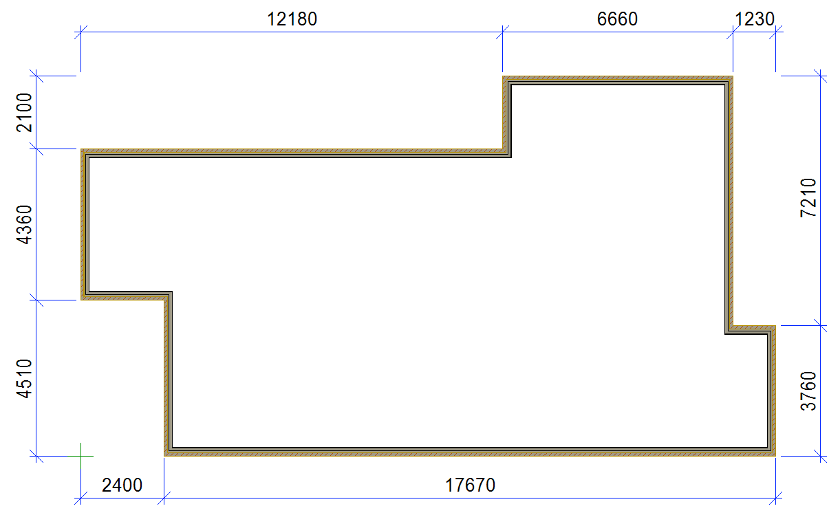
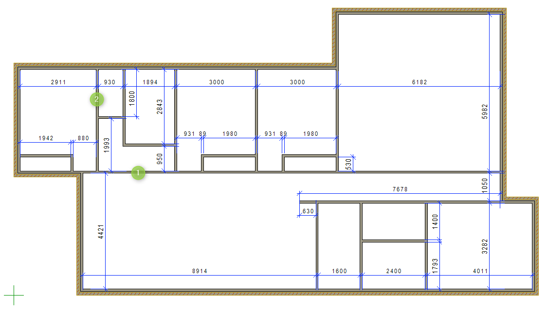
5. Draw external walls
-
We will draw the external walls of below dimensioned house.
-
Always draw walls in a clockwise order.
-
Try to start drawings from origin point

-
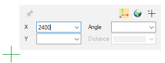
Once the wall type has been selected, Type any number and you will notice, Just as you type first number, a coordinate input dialog box opens. Type 2400 in X axis coordinate.
-
This will make the start point for this external wall 2400mm away from center of green plus sign (GDO) to the right ( in X axis ).
-
Right click on the screen ( while the cursor is in wall command ) and form the contextual menu select the wall holding position. ( i.e. inside, outside, left, middle and right etc.).
Contextual menu also lets you to manipulate Z height ( positioning height in reference to relative floor level ), holding position of wall (where you are holding the wall from, centreline or either of corners) are few functions among many others. While you in contextual menu, you can hover over each image ( hold the cursor for 1 to 2 second ), will display it's relative auxiliary function. You can select an auxiliary function even in the middle of selecting a wall point.
-
Now you can see that dotted line is the holding point of the wall.
-
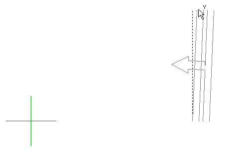
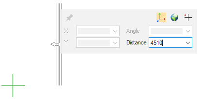
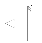
As you see Y coordinate sign, left click to lock the cursor in the Y axis.
-
After you define a direction, it is just a matter of giving distance. Type 4510 and hit enter key.
-
Once the wall is locked in the plane, it require you to pick the end point location OR type in the distance from the insertion point E.g. 2400 (mm). The command continues.
-
If you need a wall with a specific value length, you can enter the size directly; or you can also make an operation input in the input field, for example, input: 2360+2000 and hit enter.
-
Complete the other external walls.
-
To finish drawing, right click and click on OK OR press ‘V‘ OR press middle mouse button to confirm.
-
Then press ESC to exit/quit the command.
-
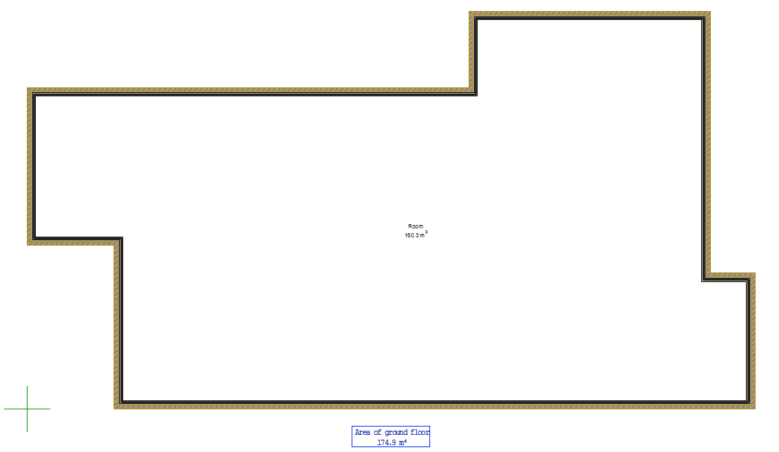
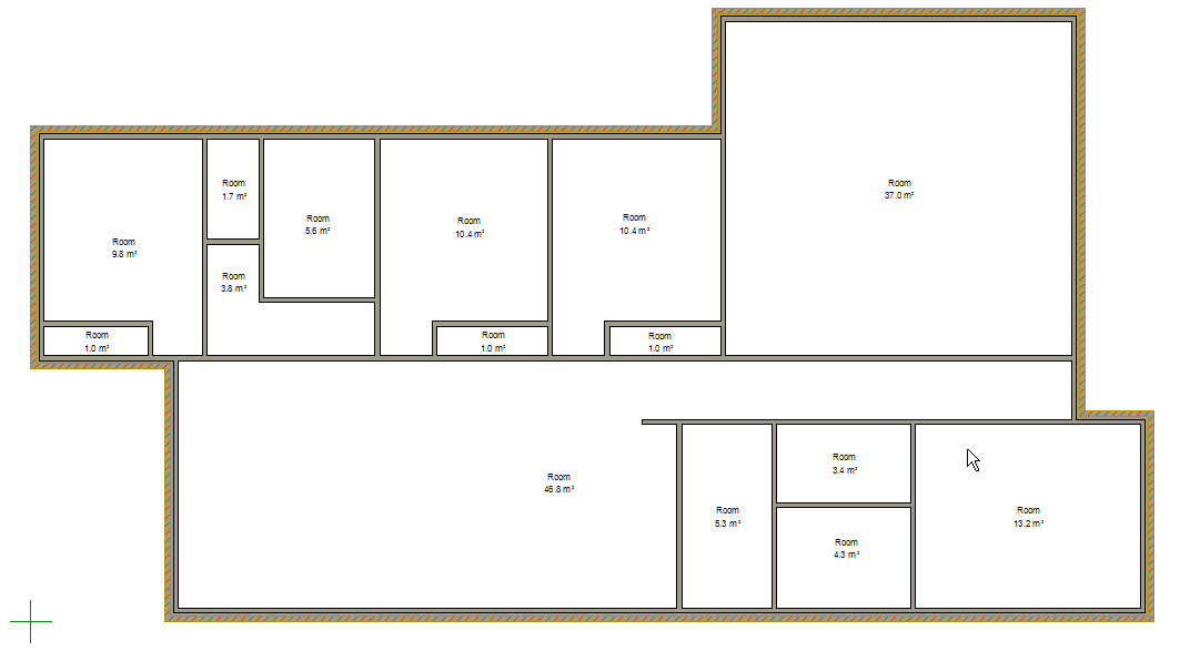
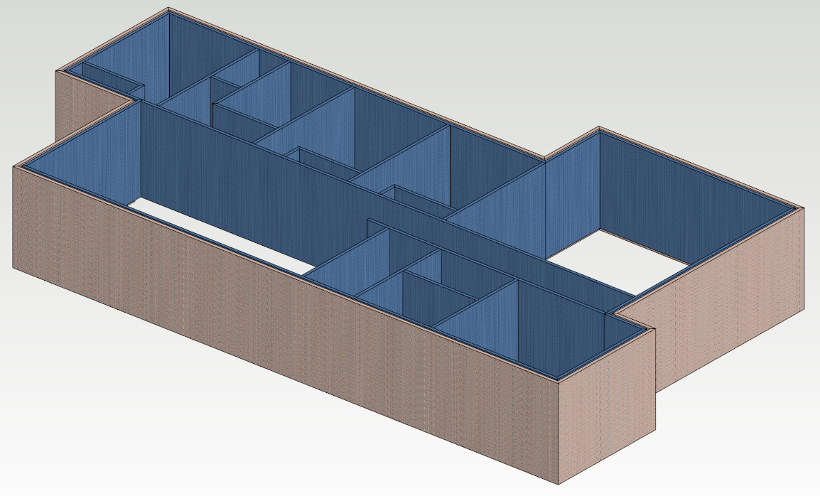
Once you have finished drawing all the external walls, you should have something like this ( shown below ). Press F2 key to switch to the 3D view
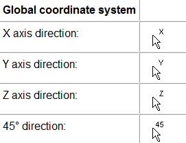
You can lock your cursor in Global coordinate system using keyboard ( U = x axis, I = y axis and O = z axis ) OR Left mouse click while you see these signs on the cursor
If you have activated the Local coordinate system, you can lock the cursor in the direction of the line defining the coordinate system, or in a model ( 3D ), in the direction of the plane.
6. Draw internal walls
-
You can draw internal wall, whichever way suits you. But for this exercise we will start with wall 1 and 2 (shown in the snapshot below).
-
Select your internal wall library and type, as instructed above.
-
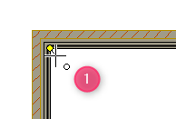
Once the wall type has been selected, hove the cursor over to the inside mid left corner of the external wall. The cursor will change to this

-
Move the cursor away horizontally so you can see the

-
Remember that you can change the holding position of the wall to suit. Just Right click on the screen ( while the cursor is in wall command ) and form the contextual menu, you can select the wall holding position. ( i.e. inside, outside, left, middle and right etc.).
-
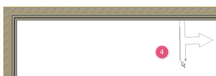
Move the cursor horizontally until cursor comes close to the internal face of end wall and you will notice this ‘/ 'symbol, left click, now the wall will be connected to internal face of the external wall
-
Remember that the cursor is still in wall command ( the command continues until you press ‘ESC‘ key to quit the command )
While you are in wall command, right click and from the contextual menu adjust / pick the holding point of wall ( i.e. inside, outside, left, middle and right etc.) as per the requirement.
-
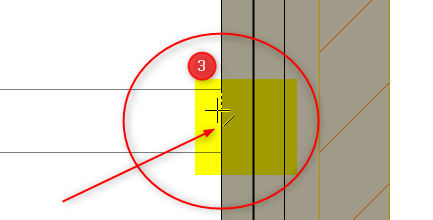
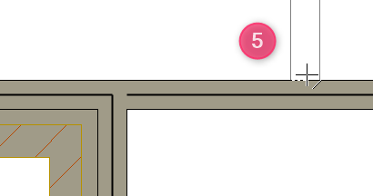
Move your cursor to hover over the inside top left corner of wall, the cursor will change to this

-
Move the cursor away to the right until you see this
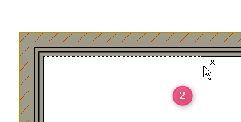
-
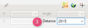
Type a number, coordinate input dialog box opens and type in distance 2911.
-
This will make the start point for this internal wall 2911 mm away to the right, from the inside face of the external wall
-
Again left click to lock the command in the Y Axis. Move the cursor in Y axis
-
Move the cursor down until you come close to the face of wall, you will notice this ‘/ 'symbol, Left click. now the wall will be connected to internal face of the external wall.
-
Remember that the cursor is still in wall command. ( the command continues until you press ‘ESC‘ to quit the command )
-
Finish drawing the rest of the internal walls.
-
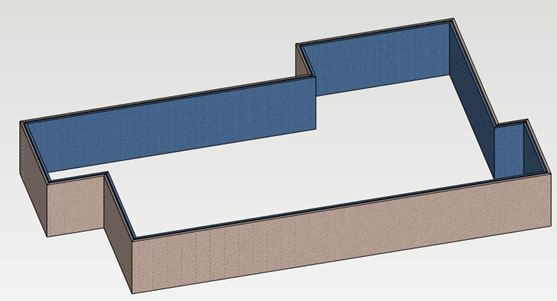
Now you should have a model that looks something like this. Press F2 to switch to the 3D view, do the same to switch back.
-
Walls can be copied. If you select the wall, once it is highlighted, right click and from the contextual menu, select ‘copy’. Pick the holding point. Lock the cursor in required axis. Type the distance and hit enter. Right click and hit OK or to press ESC exit /quit command.
-
Walls can be cut, moved, stretched and merged as per the requirement.
-
You can also use shortcut keys such as U for locking the cursor in x axis and I for locking the cursor in y axis.
-
Use O for locking the cursor in z axis. ( in 3D only)
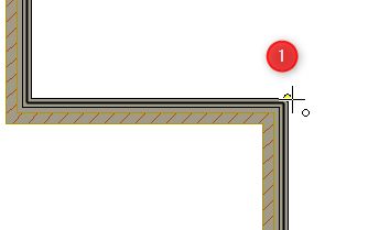
7. Check the connection at wall Junction
Generally it is a good practice to check whether the wall junctions are connected.
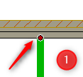
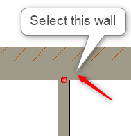
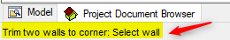
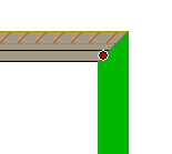
Click on the wall, once the wall is highlighted, you will notice that RED dot at the junction indicates that the wall is connected at the junction ( refer to the snapshot 1, to the right ).
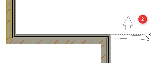
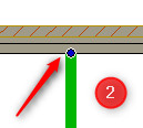
Click on the wall, once the wall is highlighted, you will notice that BLUE dot at the junction indicates that the wall is not connected at the junction ( refer to the snapshot 2, to the right ).
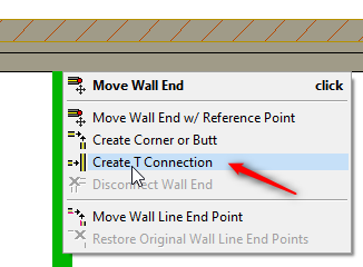
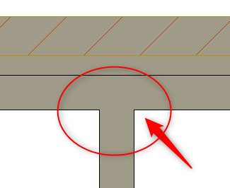
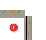
Create a T Connection: If the junctions are not connected, click on the wall, once the wall is highlighted, now hover over or close to junction BLUE dot, Right click and form the contextual menu select ‘Create T Connections’
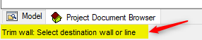
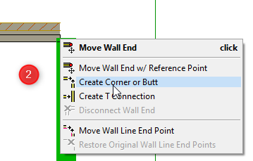
Pay attention to the instructions at the bottom left corner of Vertex window ( as shown below )
Now walls are connected at the junction.
RED dot at the junction indicates that the wall is connected at the junction
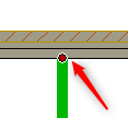
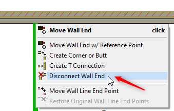
If you need to disconnect the wall for any reason, just click on the wall ( that you want to disconnect ). Once the wall is highlighted, hover the cursor over on the RED dot at the junction, right click and form the contextual menu click on ‘Disconnect wall End’
If you need to create corner, just click on the wall. Once the wall is highlighted, hover the cursor over on the blue dot at the junction, right click and form the contextual menu click on ‘Create Corner or Butt’
Pay attention to the instructions at the bottom left corner of Vertex window ( as shown below )
8. Check Wall Orientation ( Flip function )
This function is an easy way of checking which side is the exterior side of the wall. ( Matters for the accurate installation on site )
Select one or more walls (press CTRL to select more than one wall at a time OR press CTRL plus A key to select all wall in one go), Wall tab will be activated.
While wall/s are selected either from the ribbon bar or right click and from the contextual menu select this 
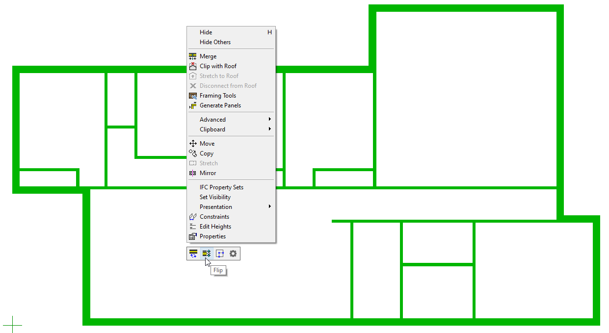
Orientation can be changed by clicking directly on these blue arrows ( side marker ).
Use shortcut keys Shift plus G to draw wall at any angle
Additional topics
How to draw walls at any angle
How to set a local coordinate system
How to draw curved wall
1. How to draw walls at any angle
Generally you can draw walls in X, Y axis and 45°.
To draw walls at any angle, you can press Shift plus G together on the keyboard.
Example scenario
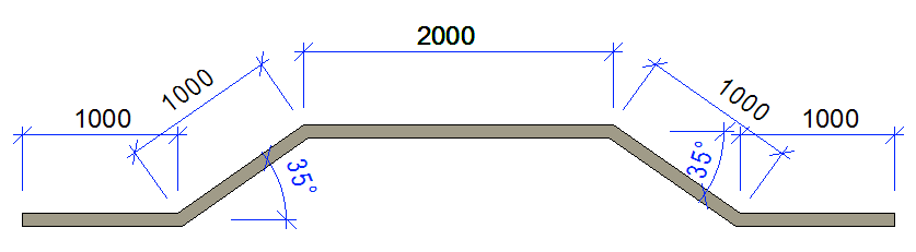
Select the wall, pick the point to draw the wall ( adjust the wall holding point if needed )
Lock the cursor in X axis
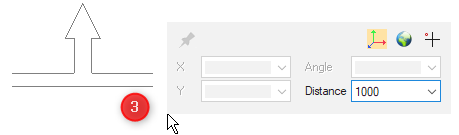
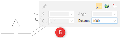
Type 1000 distance and hit enter.
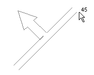
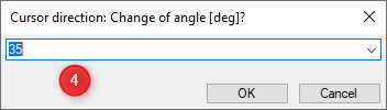
Press Shift G, direction menu pops up, type 35 click ok.
Type 1000 distance and hit enter.
Lock the cursor in X axis
Type 2000 distance and hit enter.
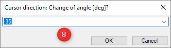
Press Shift G, direction menu pops up, type -35 click ok.
Lock the cursor in X axis
Type 1000 distance and hit enter.
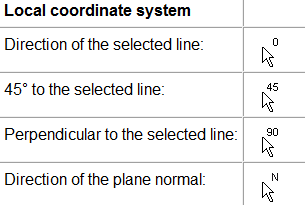
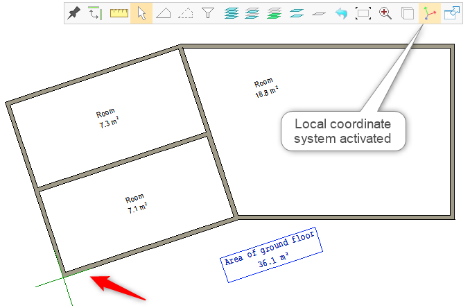
2. Local coordinate system
You can use a local coordinate system temporarily to help you design a building where not all the walls are parallel to the axes of the global coordinate system.
User have the choice to set/define the local coordinate system, which is always drawing ( 2D ) or model ( 3D )specific. Local coordinate system is not saved in the drawing or model
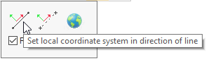
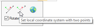
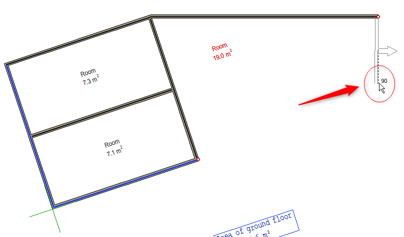
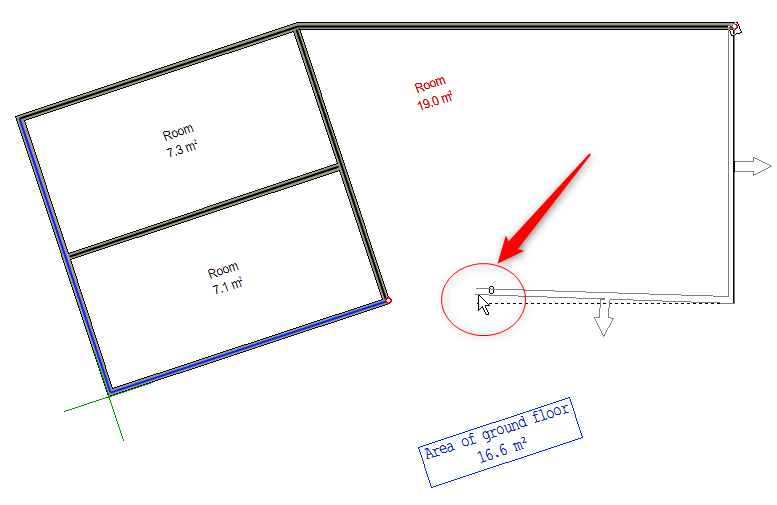
Local coordinate system enables users to lock the cursor in the X and Y axis direction of the local coordinate system, when clicking point in a drawings. You can rotate the drawing view so that the X axis of the local coordinate system is horizontal.
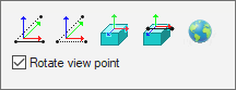
You can also set the local coordinate system in a model (3D view ), allowing you to add parts in the direction of a slanted plane of its normal. You can rotate the model view so that the XY plane of the local coordinate system is perpendicular to the viewer
Select 
Auxiliary menu in the drawing ( 2D )
If you hover over the over the images in the auxiliary menu it will display a relative function.
Auxiliary menu in the drawing ( 3D )
To remove the local coordinate system and return to the global system, Select 
When the local coordinate system is in use, tool strip icon for set local coordinate system changes to this 
Global coordinate system
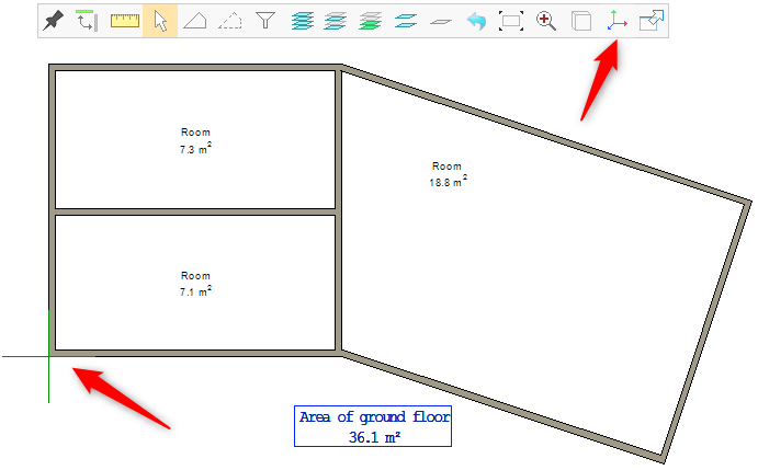
Local coordinate system activated
Local coordinate system activated
Local coordinate system activated
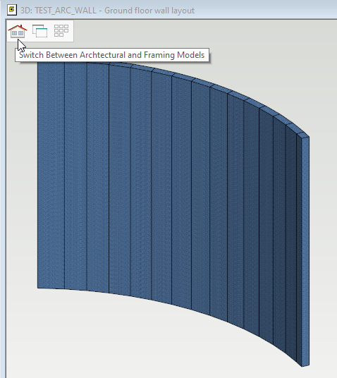
3. How to draw curved wall
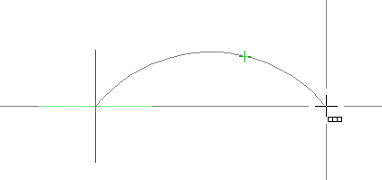
You can also draw curved walls. Select Arc with three points under Drafting tab.
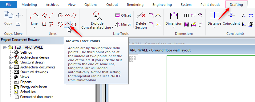
Change the cursor to cross line cursor by pressing Shift plus H. It is not a hard rule but helpful in this case ( you can change back to normal cursor any time by pressing Shift plus H again )
Draw a arc line ( select point 1, 2 and 3 )
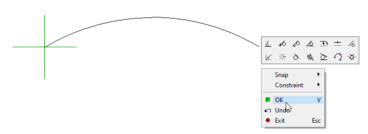
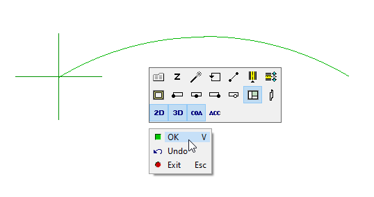
When you have finished adding arc lines, right-click and click on OK to confirm.
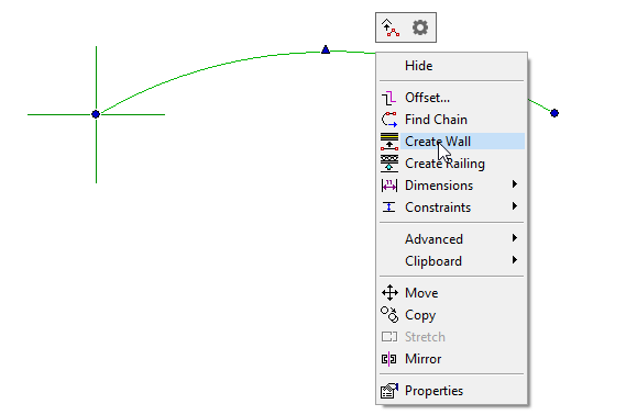
Select the arc line and right click and form the contextual menu click on 'Create Wall'.
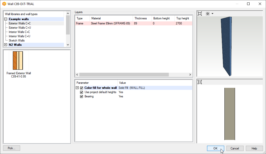
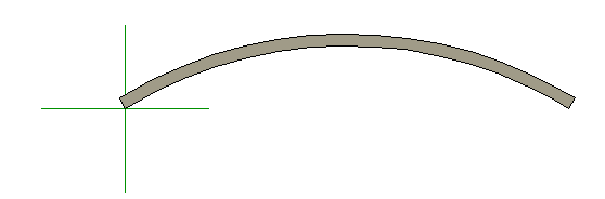
The Wall Library dialog pops up, select the wall type and click OK .
Right click in the blank area and select OK.
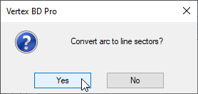
Dialog window pops up, Convert the arc to a line segment ? Click on'Yes' .
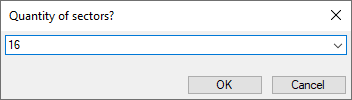
Dialog window pops up, Enter the number of panels you want to divide the arc wall into.
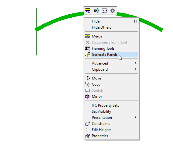
Select all curved walls, right click and select the Generate Panels.
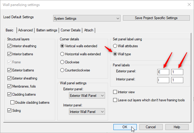
Wall panelizing settings window opens, Tick ON the the wall type check button, panel labels initial and click OK
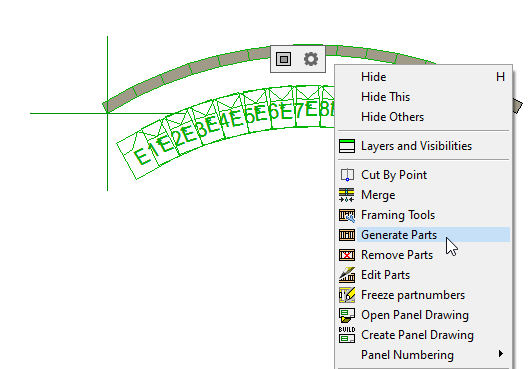
Select all curved walls, right click, and select the Generate Parts.
Press F2 to switch to 3D view