-
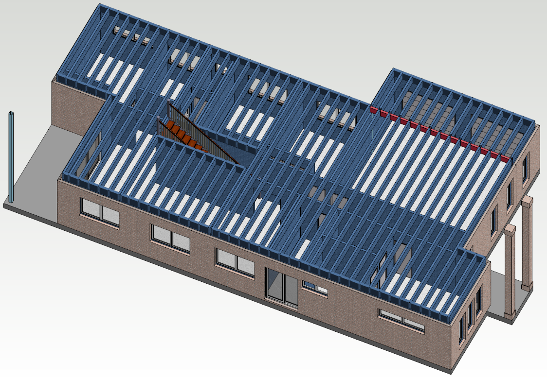
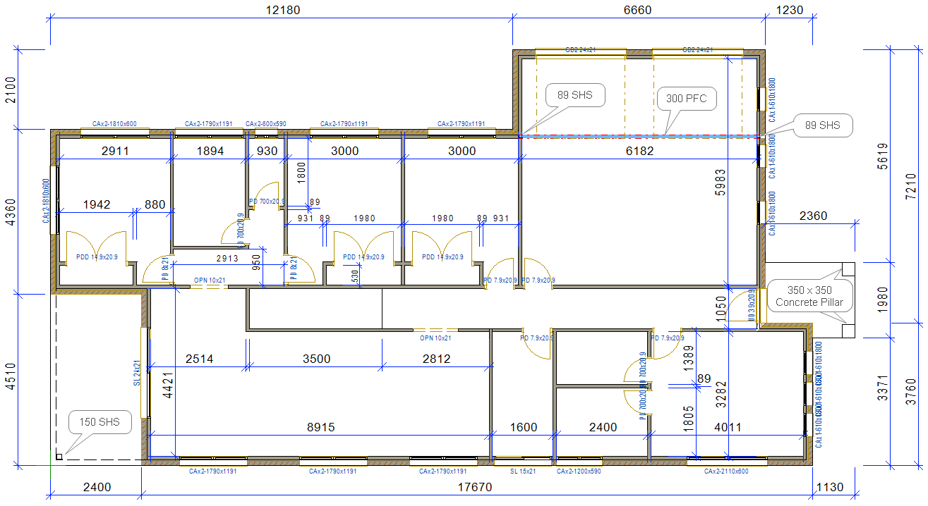
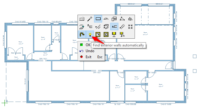
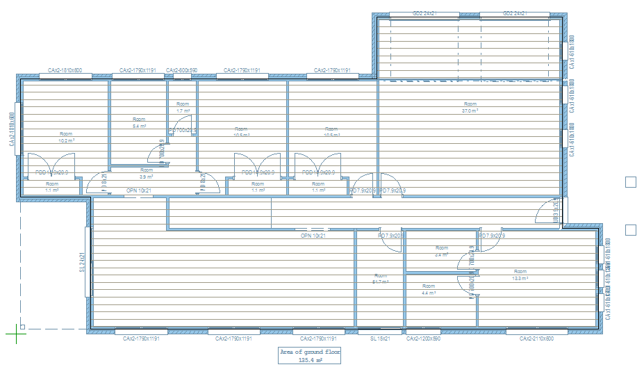
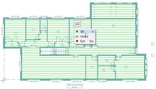
For this exercise we have designed ground floor as shown below ( Refer to Vertex BD Pro 2020 Training Manual Part-1 ( Basic Training ) for details about how to add Walls and openings etc. to a model )
-
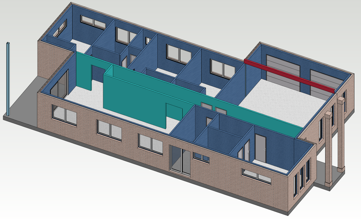
Internal load bearing walls are highlighted.
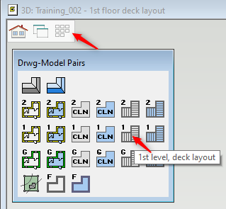
Switch to 1st Level deck layout
-
Before drawing the floor you need to switch to 1st Level deck layout.
-
In case you are in 3D view just press 'F2' to switch to 2D view.
Add Reference Drawings or Set visibility
-
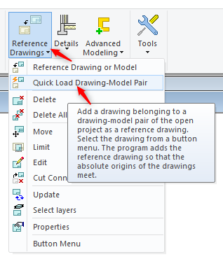
In 'Modelling' tab Add ‘Reference Drawings’ → ‘Quick Load Drawing-Model Pair’.
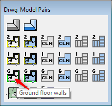
Or Set Visibility
-
Select 'Ground floor walls', since you want to add mid floor over it.
Check 3D Levels
-
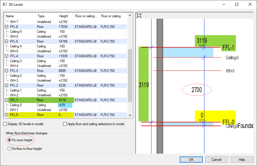
Before you add the mid floor, make sure that the floor / room height and floor thickness is set to suit or as per the requirement.
-
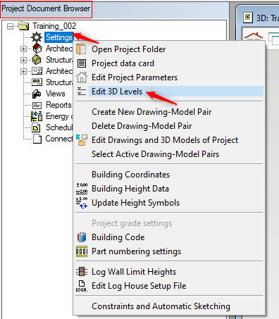
In 'Project Document Browser' select 'Settings' right click and from the contextual menu select 'Edit 3D Levels'
-
So we have fixed 2700mm room height and 419 deep mid floor ( 400 deep floor trusses and 19mm yellow tongue floor board.
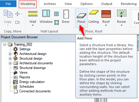
Add Floor to 1st Level deck layout
-
In 'Modelling' tab click on Floor icon.
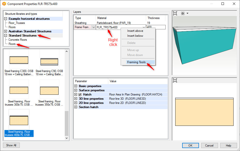
-
Select 400mm deep floor as shown
-
Change the sheeting to 'Particleboard floor 19' ( 19mm thick )
-
Select the frame, right click and click 'Framing Tools'
-
and click OK.
-
Change the tool to 'Steel Framing ( FLR_C89 )' and click OK.
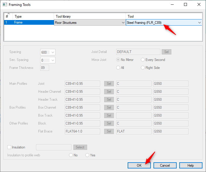
-
click OK.
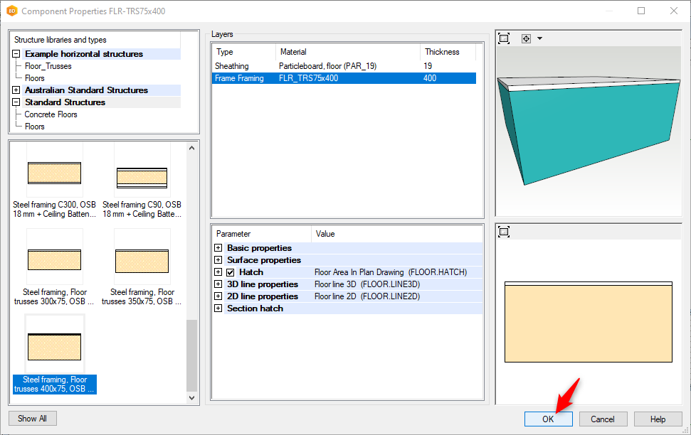
-
Right click on the screen and the Contextual menu pops up ( as shown ) that lets you check the floor level and select the floor area by points or by walls
-
Now the floor have been added on ground floor.
-
Press ESC to exit the floor command.
-
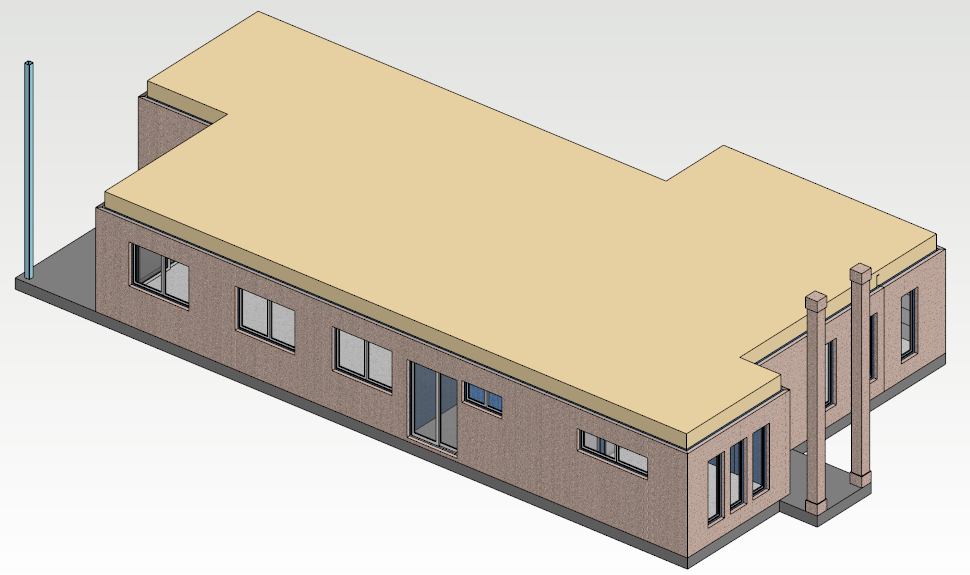
Press 'F2' to switch to 3D view
Create Stair void / Whole in the floor
-
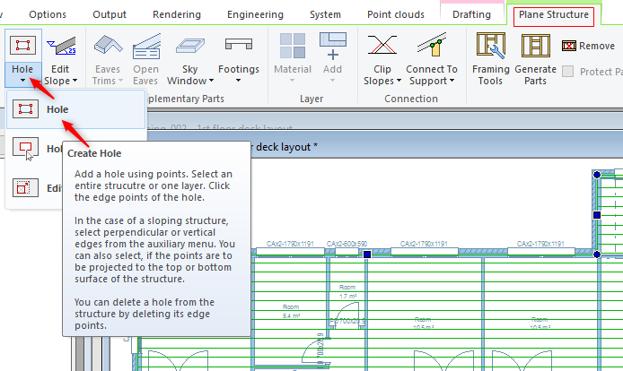
Change to 1st Level, deck layout drawing pair and in 2D view. and 'Plane Structure' tab get activated.
-
Select Hole icon and 'Hole'
OR
-
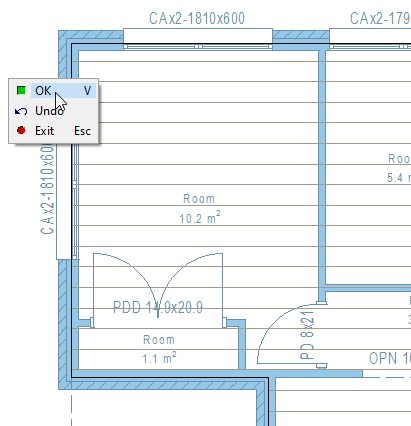
Select the floor, right click and from the contextual menu select ‘Create Hole’.

-
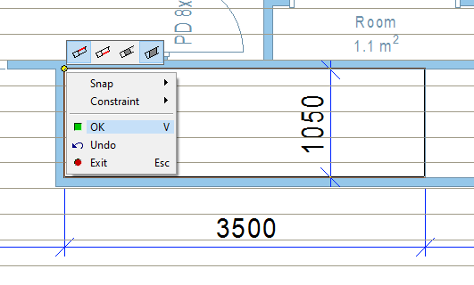
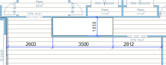
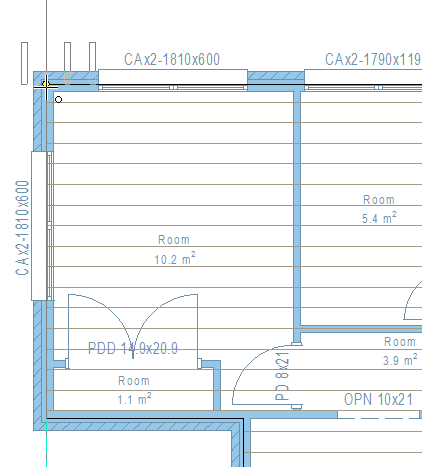
Pick a rectangular point ( as per the dimensions shown ) at the end right click and confirm. Or hit ‘V’.
-
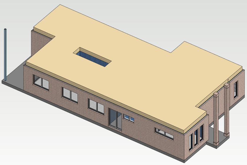
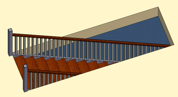
You should have stair void hole in the floor as shown.
-
Press 'F2' to switch to 3D view
Add Stair
-
We will now create the stair. Change to ‘Ground Floor walls’ Layout drawing pair.
-
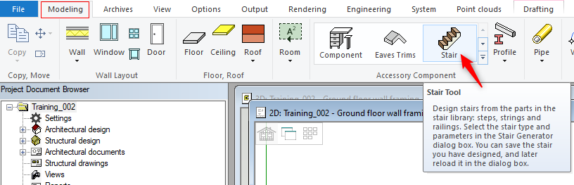
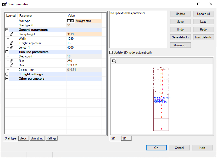
In ‘Modelling’ tab’, select ‘Stair’ icon form the ribbon Or Right click and select the ‘Stair Tool’.
-
Fill out as per the dialog box and click OK
-
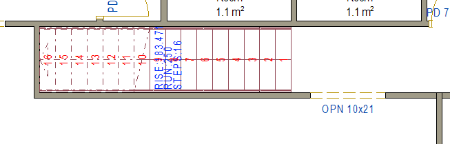
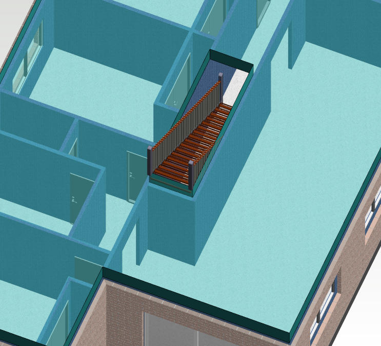
Rotate the stair with the arrow keys for correct position ( As shown ).
-
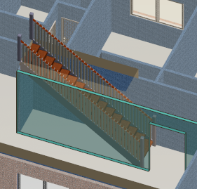
Press 'F2' to switch 3D view to ensure the stair is in the correct position.
Use shortcut key 'W' on the keyboard to see through the surface.
You can also select an object through a surface in the model by pressing the 'W' key.
This is a one-off function, so you have to reselect it, if you want to select more objects through a surface
-
Select an object or profile. ( Hold down the CTRL key to select several profiles )
-
Right-click to open the context-sensitive menu.
-
Select Trim to Plane.
-
Move the cursor over the surface, which you want to select through.
-
Press the 'W' key. The program will make the nearest surface transparent. Keep pressing the 'W' key until the desired surface is visible.
-
Click the surface.
-
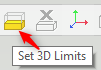
You can all also set 3D limits
Create Floor Joists ( Floor Trusses )
-
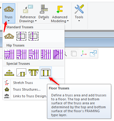
Now we can create 400 deep Floor Trusses. You can use this function ( shown below ) to define a truss area and to add trusses to a floor. The top and bottom surface of the truss area are determined by the top and bottom surface of the floor's FRAMING type layer.
-
Change to 1st Level, deck layout drawing pair.
-
In ‘Modelling’ tab → Truss → Floor Trusses
-
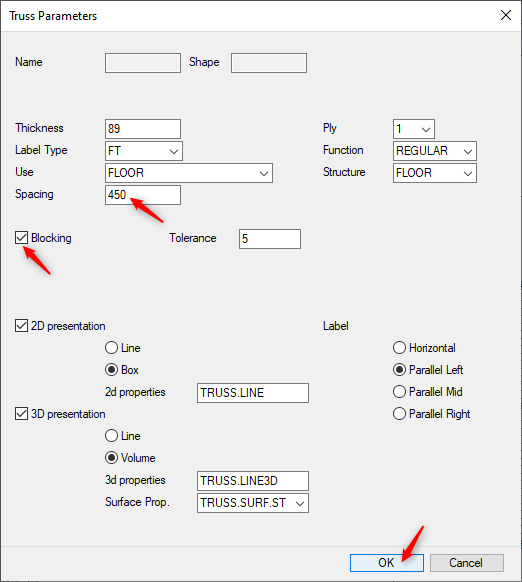
'Truss Parameters' dialogue box appears.
-
Label type can be changed but here we will only change Spacing to 450 Centers.
-
In this exercise we want to use blocking between the floor trusses ( by the external walls / end of floor truss ). So Tick 'Blocking' and 5mm tolerance at each end ( can be changed as per the requirement )
-
Click OK.
-
Vertex prompts you to Select area. Right click and click OK to confirm or press 'V' to confirm
-
Before you click the start point of the truss spacing, you can change the direction of the line as follows:
-
Press the Arrow Right or Arrow Left key.
-
Right-click to open the context-sensitive menu and select one of the following:
-
Vertical
-
Horizontal
-
Default (direction of the riser on a sloping plane)
-
Select direction
-
Select the start point of the direction line.
-
Select the end point of the direction line.
-
-
-
-
Do either of the following:
-
Select the point from which the truss spacing will be started. The trusses will be divided in both directions starting from the selected point.
-
Select Confirm. The positioning of the trusses will be started from the left edge of the area (trusses in the y axis direction) or from the top edge (trusses in the x axis direction).
-
-
Locate the first truss, ( click at the corner as shown ). Right click and click OK to confirm
-
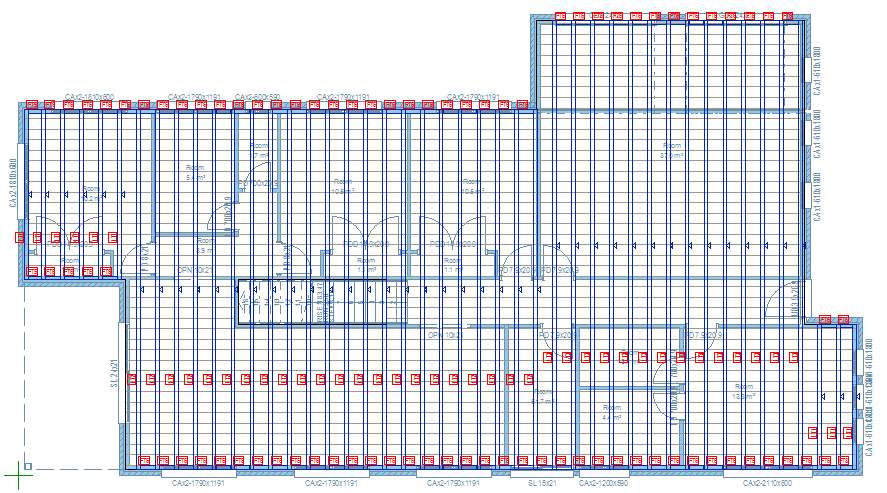
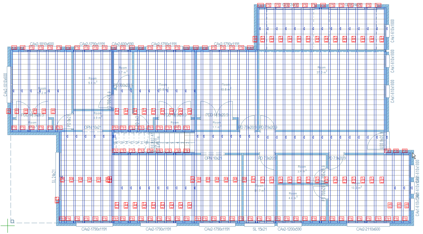
Now we have created floor Truss envelope, spacing at 450mm centers max.
-
You can copy, cut and drag the Floor until it look something like this
-
Press 'F2' to switch to 3D view