Create configuration to part model
An example structure in Flow is shown underneath.
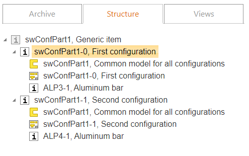
In this example part model defines 2 items: swConfPart1-0 and swConfPart1-1, where the first has material ALP3-1 and the second has ALP4-1 in the Flow item structure. Both items have their own drawings. Configurations may also differ e.g. in geometry or some other aspect like with normal SolidWorks configurations.
It is not required to end the code with a configuration number (e.g. swConfPart1-0) as in the example. You can use any sequential numbers instead: VX3001234, VX3001235 ...
Generic item swConfPart1 is not mandatory and cannot be used as a part in Flow structure or SW assembly, but it helps to see available variant items swConfPart1-0 and swConfPart1-1. Symbol of swConfPart1 item turns grey when you fill variant fields in item structure and check-in parent item.
Three steps to create configurations and link Flow items to them:
1. In SolidWorks user interface
-
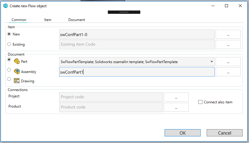
create the first Flow variant item swConfPart1-0 and part model swConfPart1 with create a new Flow object function
-
with browser: drag material item ALP3-1 to part model.
-
create drawing swConfPart1-0 to model.
-
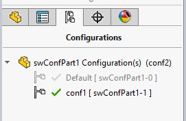
add a new configuration to the model with the name conf1 in SolidWorks configurations tab
-
check-in all to Flow
2. In Flow
-
browse item swConfPart1-0
-
set metadata to item swConfPart1-0: SW configuration = Default
-
copy item swConfPart1-0 -> swConfPart1-1: item->copy
-
Set metadata to a new item: SW configuration = conf1
-
link new item to a common model of all configurations: swConfPart1.
-
link new item to drawing if all configurations have a common drawing: swConfPart1-0
-
-
create a generic item swConfPart1 and add to its structure items swConfPart1-0 and swConfPart1-1. More information about creating generic items can be found in Flow documentation.
-
set structure items of generic item swConfPart1 as variants 0 and 1
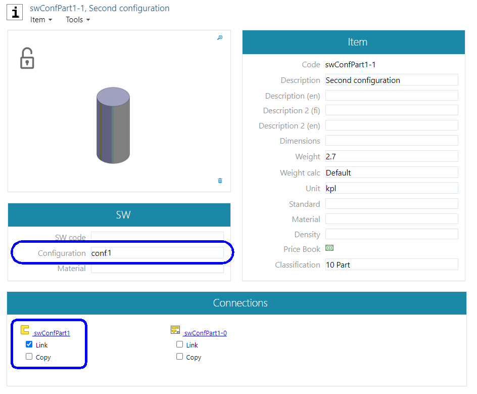
Set ConfPart 1-1 metadata
If you have created many configurations to the part and the configuration field in Flow is empty, the program uses default configuration when adding the part to an assembly
3. In SolidWorks user interface
-
open item swConfPart1-1 and its model
-
with browser: drag material item ALP4-1 to part model.
-
create drawing swConfPart1-1 to model if both configurations do not have a common drawing
-
check-in all to Flow
Create configuration to assembly model
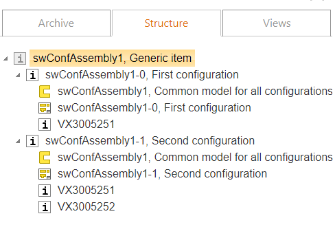
In this example assembly model defines 2 items: swConfAssembly1-0 and swConfAssembly1-1, where the first has one part VX3005251 and the second has two parts VX3005251 and VX3005252 in the Flow item structure. Both items have their own drawings.
It is not required to end the code with a configuration number (e.g. swConfAssembly1-0) as in the example. You can use any sequential numbers instead: VX3001234, VX3001235 ...
Generic item swConfAssembly1 is not mandatory and cannot be used as a part in Flow structure or SW assembly, but it helps to manage available variant items swConfAssembly1-0 and swConfAssembly1-1. The symbol of swConfAssembly1 item turns grey when you fill variant fields in item structure and check-in parent item.
Three steps to create configurations and link Flow items to them:
1. In SolidWorks user interface
-
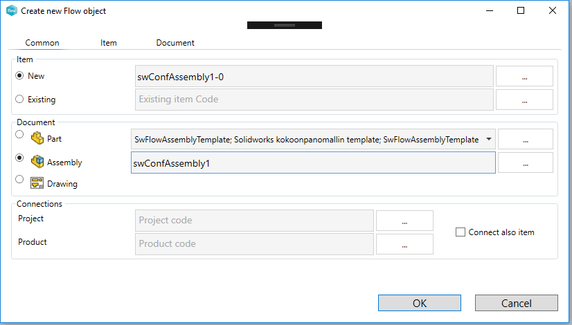
create first Flow variant item swConfAssembly1-0 and assembly model swConfAssembly1
-
add items VX3005251 and VX3005252 to assembly
-
create drawing swConfAssembly1-0 to model
-
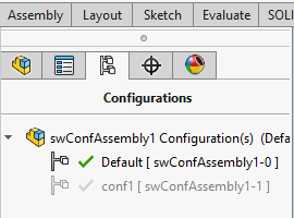
add a new configuration to model with name conf1 in SolidWorks configurations tab
-
check-in all to Flow
2. In Flow
-
set metadata to item swConfAssembly1-0: configuration = Default
-
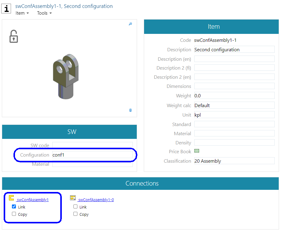
copy item swConfAssembly1-0 -> swConfAssembly1-1
-
set metadata to a new item: SW configuration = conf1
-
link new item to a common model of all configurations: swConfAssembly1
-
link new item to drawing if all configurations have a common drawing: swConfAssembly1-0
-
-
create generic item swConfAssembly1 and add to its structure items swConfAssembly1-0 and swConfAssembly1-1. More information about creating generic items can be found in Flow documentation.
-
set structure items of swConfAssembly1 as variants 0 and 1
3. In SolidWorks user interface
-
open item swConfAssembly1-1 and the model
-
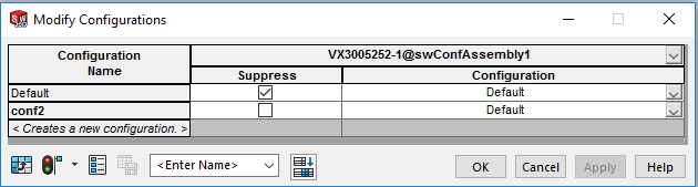
at SW's configure component dialog: set model VX3005252 suppressed at the default configuration
-
create drawing swConfAssembly1-1 to model if both configurations do not have a common drawing
-
check-in all to Flow