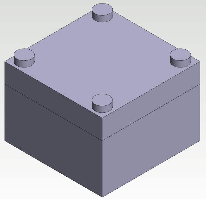
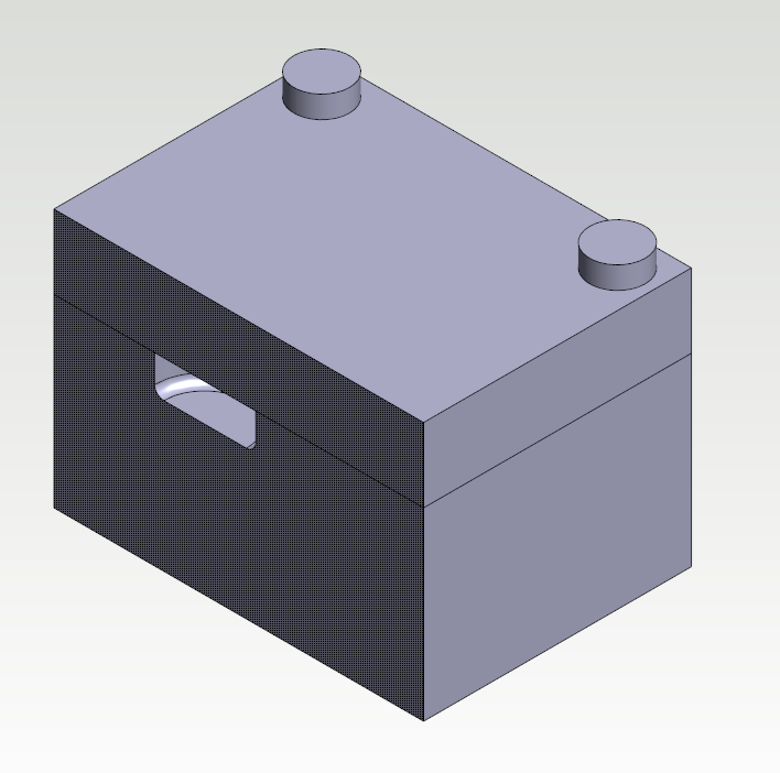
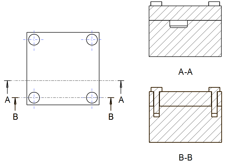
This example shows how to analyze a pressured block with a bolted cover. The cavity in the block is pressurised by 300 bar. The cover is bolted to the block and the bolts have pretension of 20 kN.
The aim of the analysis is to examine how big gap there will be between the block and cover when the block is pressurised.
Create a new study
-
Open model Ex_FEA_Solid_2 from project Examples. Go to FEA state by selecting FEA >

-
Create a new study by selecting

-
Fill study information.
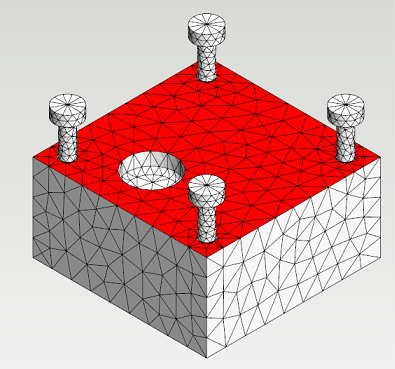
Edit element mesh
-
Open FEA Mesh settings dialog by pressing

-
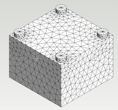
Hide the cover by hovering a mouse cursor over it and pressing H. The element mesh in the cavity is too dense because only the displacements of the cover will be examined in this study.
-
Set maximum growth rate value of 2 for surface and 6 for interior. Press Apply. Now the element mesh is coarse enough and the calculation time will be shorter.
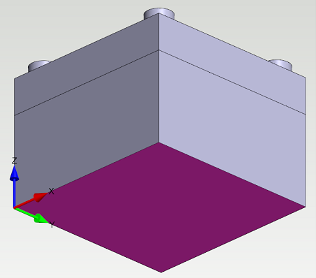
Set supports, contacts and loads
-
Select the bottom surface of the block. Set the support preset


-
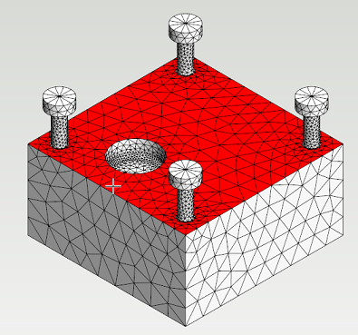
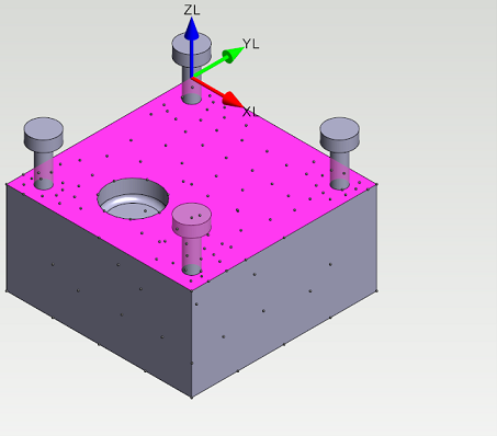
Hide the cover and select the upper surface of the block. Press Local Coordinate System from the ribbon tab. Define the surface as contact surface by pressing Contact from ribbon tab.
-
Change the X and Y degrees of freedom


-
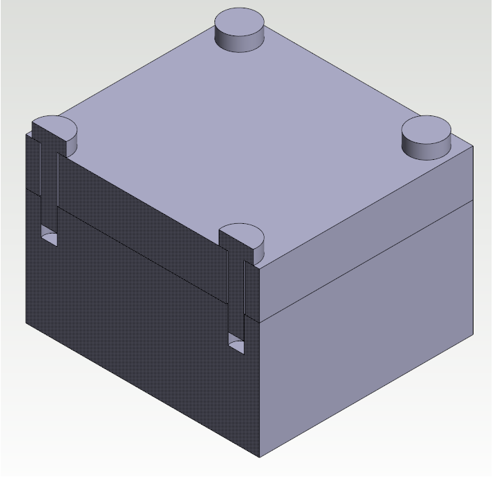
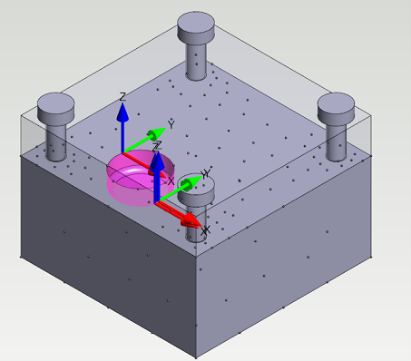
Select all surrounding surfaces of the cavity. Set pressure of 30 MPa (300 bar) for all selected surfaces.
-
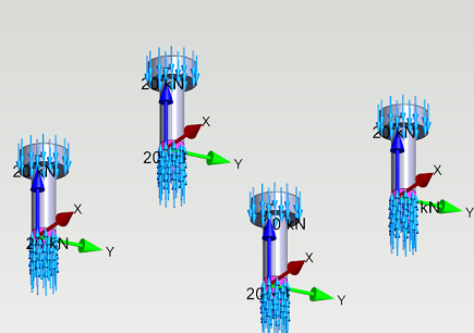
Hide the block and the cover. Select the bottom surfaces of bolt heads and the threaded surfaces of bolt rods. Set force of 20 kN to selected surfaces to model the pretension in bolts. These surfaces are not defined as contact surfaces and they are fixed to connecting faces. The pretension force will now compress the cover against the block.
Solve the study
-
Select

-
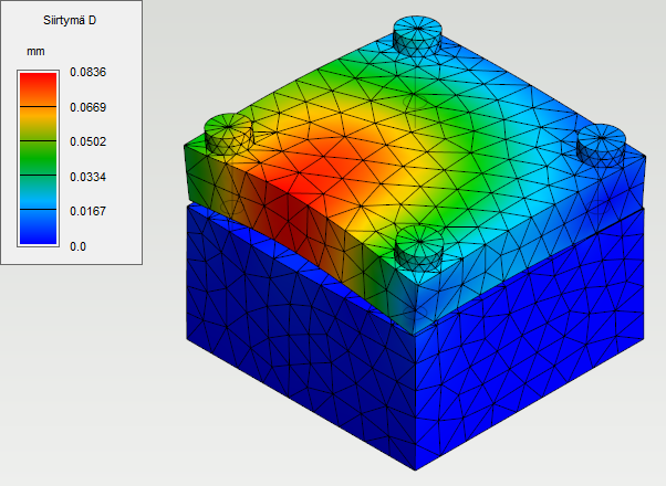
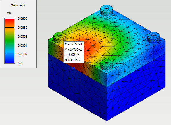
Change the stress plot to Displacement. The displacements of structure can be visualized with Displacements slider. The gap between the block and the cover is approximately 0.0856 mm.