Beams and Frames: Nodes
Node states
Node states are unlinked node, the main node and linked node.
- Unlinked node is shown as a green ball in 3d model.

- The main node is shown as a bigger blue ball in 3d model.

- Linked node is shown as a blue ball in 3d model.

- Linked nodes are connected with blue line between the nodes.
Type of connected node can be Rigid Link or Master-slave.
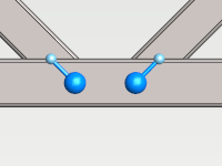
- node with Rigid Link is shown in dark blue color in 3d model.
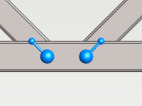
- Linked node with Master-slave is shown in light blue color in 3d model.
Select nodes
Nodes of active study can be selected from 3d model.
- Node is selectable when a small circle appears next to the cursor.
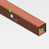
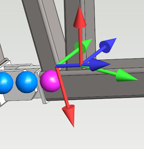
- The coordinate system of selected nodes are shown in 3d model.
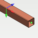
- Hold Ctrl to select multiple nodes.
- Node selection can be cleared by clicking empty space from 3d model or pressing Esc.
Visible and selectable nodes can be filtered by selecting parts of active study. Only nodes belonging to selected parts are visible and selectable.
Set the coordinate system of the node
- Select nodes.
- Press Local Coordinate System checkbox from the ribbon tab.
- When the checkbox is checked, the coordinate system of the node is the main principal coordinate system of the part's cross section.
- When unchecked, the coordinate system is the global coordinate system of 3d model.
In local coordinate system
- X axis coincides with beam neutral axis
- Y axis coincides with the first main direction of the cross section
- Z axis coincides with the second main direction of the cross section
By default in new studies all nodes have local coordinate system set.
Set the degrees of freedom for nodes
- Select nodes.
- Press

- Supports and link definitions are set always in the selected coordinate system of the node
Support options and their descriptions for unlinked and main node are listed in the table below
Symbol in ribbon tab Support definition Description 
Free The degree of freedom is free to translate or rotate in the solution. 
Fixed The degree of freedom is fixed to place in solution. Its translation or rotation is zero. Link options and their descriptions for linked node are listed in the table below
Symbol in ribbon tab Support definition Description 
Free The degree of freedom is free to translate or rotate in the solution. 
Linked The degree of freedom is linked to the main node in the solution.
Link nodes
- Select unlinked nodes which are going to be linked.
- Press

- The preset for link can be selected from five options.


- Type of the link can be defined as Rigid Link or Master-Slave.
The firstly selected node will be the main node. The main node is marked in violet color in the model when the Link nodes dialog is open.
- The other selected nodes will be linked nodes with selected link preset.
- The preset for link can be selected from five options.
Unlink nodes
- Select nodes.
- Press

- Selected nodes will be changed to unlinked nodes.
Change the main node of link
- Select linked nodes which are going to be main nodes.
- Press Main node checkbox from the contextual ribbon tab.
Linked group of nodes can have only one main node.
Change the type of the link
- Select nodes which type are going to be changed.
- Select from the contextual tab option


Set support or link preset
- Support preset can be set for unlinked nodes or main nodes.
- Select nodes.
- Select support preset and possible extra definition from contextual tab.
- Descriptions of presets are listed in the table below
| Support preset | Extra definition | Description |
|---|---|---|
 | All degrees of freedom of node are  | |
 | All degrees of freedom of node are  | |
 |
| The rotational degrees of freedom defined by extra definition are   |
- Link preset can be set for linked nodes.
- Select nodes.
- Select link preset and possible extra definition from contextual tab.
- Descriptions of presets are listed in the table below
| Link preset | Extra definition | Description |
|---|---|---|
 | All degrees of freedom of node are  | |
 |
| The rotational degrees of freedom defined by extra definition are   |


