
The active study can be solved by pressing 
Change the stress plot
-
The presented stress plot can be changed from the Stress plot list of FEA results dialog.
-
Descriptions of different stress plots are listed in the table below
|
Stress plot |
Unit |
Description |
|---|---|---|
|
Axial force N |
kN |
Force in the direction of beam axis |
|
Torsion moment MT |
kNm |
Force about the direction of beam axis |
|
Bending moment MY |
kNm |
Bending moment about the first main direction of cross section |
|
Bending moment MZ |
kNm |
Bending moment about the second main direction of cross section |
|
Shear force QY |
kN |
Shear force in the first main direction of cross section |
|
Shear force QZ |
kN |
Shear force in the second main direction of cross section |
|
Normal stress |
MPa |
Normal stress in the direction of beam axis is calculated as follows:
|
|
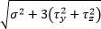
Von Mises stress |
MPa |
Von Mises stress is calculated from normal and shear stress components with following formula In the formula, σ is normal stress in the direction of beam axis and τ are shear stresses in the main directions of cross section. Shear stresses are composed of
Von Mises stress calculation is inaccurate because the distribution of shear stress in the cross section area is not precisely known. In most cases it gives a bit too high value. |
|
Displacement D |
mm |
Displacement resultant of beam neutral axis |
|
Displacement DY |
mm |
Displacement in the first main direction of cross section |
|
Displacement DZ |
mm |
Displacement in the second main direction of cross section |
|
Twist |
mrad |
Twist of beam axis |
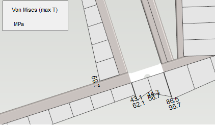
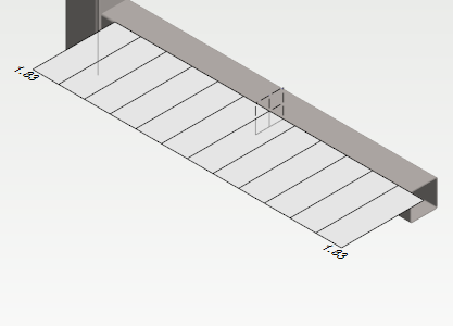
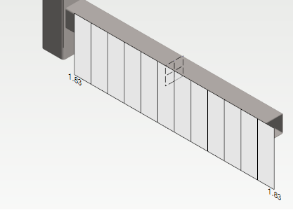
Visualize displacements
-
The displacements of structure can be visualized by dragging Displacements slider.
-
The displacements of structure is shown in 3d model.
The visualization of displacements is not shown in real scale. The displacements are shown exaggerated.
Modify the visualization of results
Change results display
-
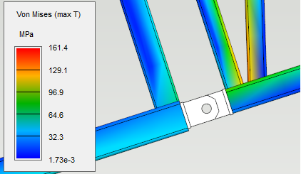
Results display can be selected as Colored or Diagram.
-
The scale of diagrams can be modified by setting Scale factor.
Show support reactions
-
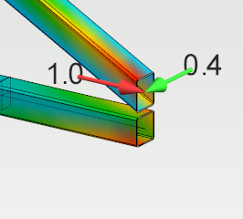
Set Show support forces on. Support force components are shown on supported nodes in unit kN.
-
The coordinate system for shown support force components can be selected as local coordinate system of node or global coordinate system of 3d model.
-
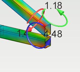
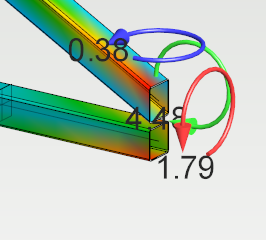
Set Show support moments on. Support moment components are shown on supported nodes in unit kNm.
-
The coordinate system for shown support moment components can be selected as local coordinate system of node or global coordinate system of 3d model.
Show connected nodes
-
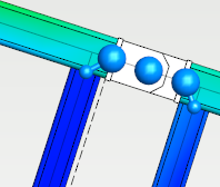
Set Show connected nodes on. The linked nodes and the main nodes of active study are shown.
Hide profiles
-
Set Hide profiles on when diagram results display is selected. The geometry of parts in active study is hidden.
-
Nodes and neutral axes of parts are shown instead of geometry of parts.
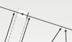
Rotate representation plane
-
Rotate representation plane option is possible for stress plots which direction can not be expressed with the directions of cross section main directions. These stress plots are
-
Axial force N
-
Torsion moment MT
-
Normal stress
-
Von Mises stress
-
Displacement D
-
Twist
-
-
When Rotate representation plane option is turned on and some of the stress plots above is selected, the representation plane of diagram is aligned with the first main direction of the cross section.
-
By default the representation plane of diagram is aligned with the second main direction of the cross section.
-
The global directions for shear forces QY, QZ and displacements DY, DZ can be seen from the vertical axis of diagram.
-
The global directions of bending moments MY and MZ can be seen from the normal of representation plane.
Save view
-
The results view can be saved by pressing Save view. The background color can be changed to white if wanted.