

Exercise 8: How to create drawings from the assembly
The main objective of this exercise is to a simple layout drawing from the main assembly.
The estimated time to complete this exercise is 5 minutes.
This exercise was carried out with Vertex G4Plant 31.0 (2025).
In this exercise, you will learn to
-
How to create a drawing from the model
-
How to modify and add projections to the drawing
-
Annotations
-
Parts list
Functions in Use
-
Drawings > Context-sensitive function: New Drawing
-
Archive data
-
Refresh (F5)
-
Save
Open the model of your main assembly
-
Open the model of your main assembly (EXP-MAIN.vxm) from the previous exercise.
-
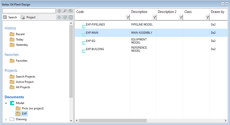
Open the basic browser by pressing B and find the segment Documents.
-
The segment Documents divides into two main branches Model and Drawing.
-
Search the folder of your project from the branch Model. Then double-click it to open the model.
-
You can find more information about the browser here.
If necessary, repeat the exercise how to create the model's drawing
How to create a new assembly drawing
Create the model's drawing
-
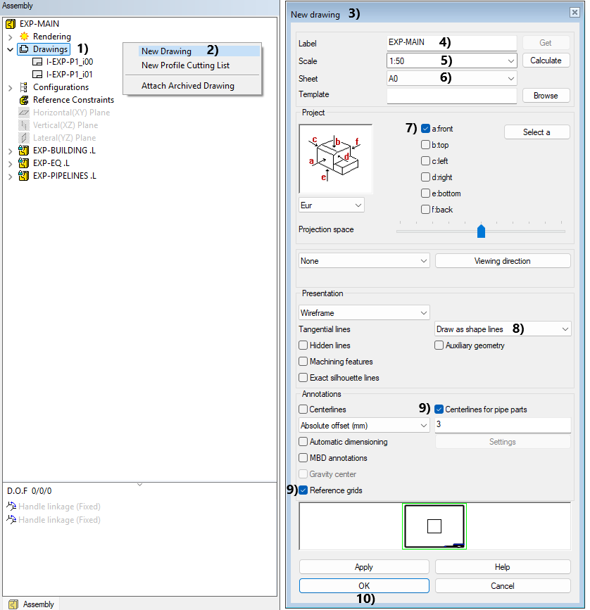
First, select Drawings from the assembly tree, in picture 1).
-
Then a context-sensitive function: New Drawing, in picture 2).
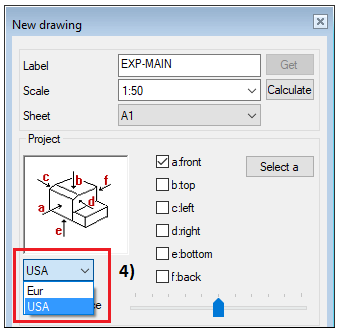
At the window New drawing, in picture 3):
-
Label: The program proposes a label EXP-MAIN. Rename it if wanted, in picture 4).
-
Scale: 1:50, in picture 5).
-
Sheet: A0, in picture 6).
-
Select the projection: a: front, in picture 7).
-
Tangential lines: Draw as shape lines, in picture 8).
-
Enable the check-boxes: Also pipe parts and Reference grids, in picture 9).
-
OK, in picture 10).
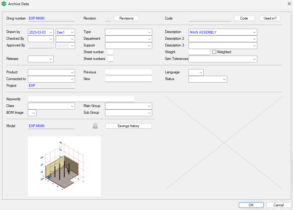
At the window Archive data:
-
The drawing inherits the archive data from the model. You can modify the data or leave it as it is.
-
OK > The drawing opens and is saved to the archive. Do this.
-
Cancel > The drawing opens and it isn't saved to the archive.
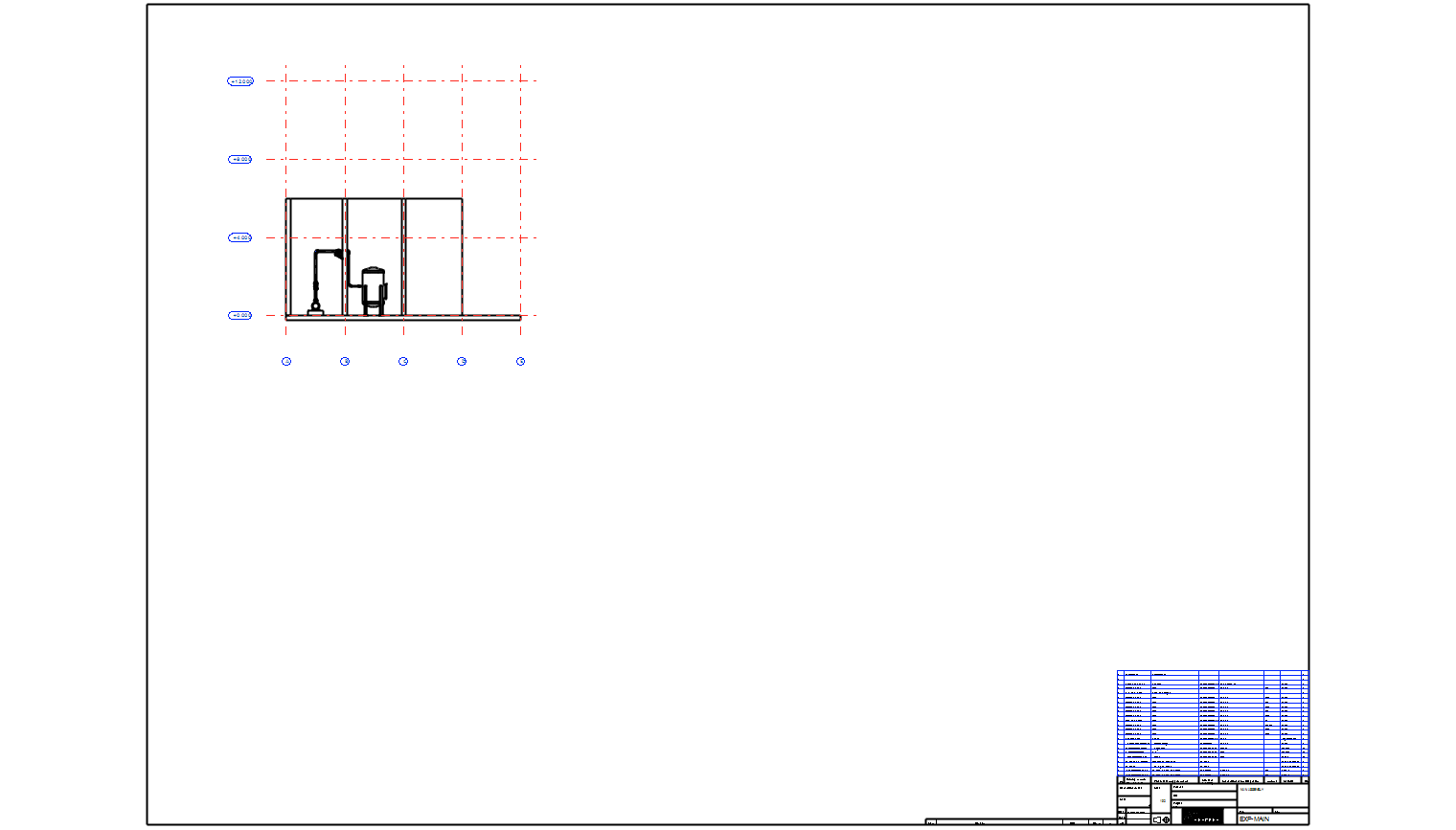
Place the projection in the upper left corner of the drawing
Move the projection
-
Move the cursor close to the front projection
-
Press the left mouse button and keep it pressed. Drag the projection to the upper left corner of the drawing.
-
Lift the left mouse button when the projection is at the correct place.
Move the sheet
-
Instead of moving projections, you can also move the sheet by dragging it as you did with the projection.
-
Once the sheet is in the correct place, refresh the drawing by pressing F5 from your keyboard.
Make a top view
-
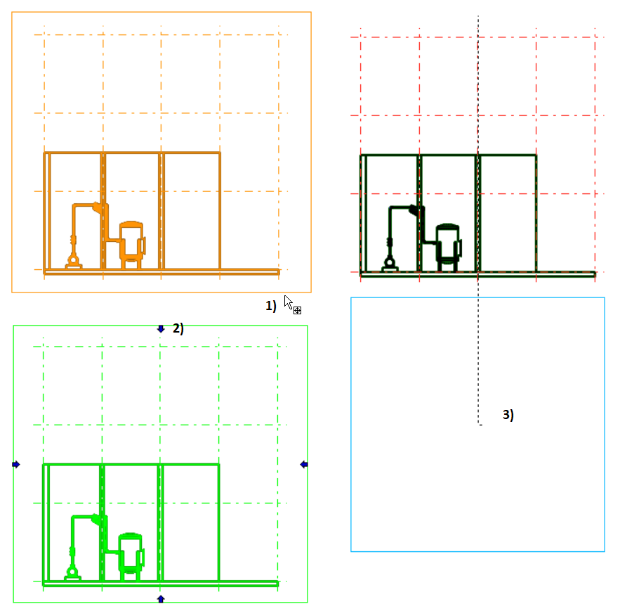
Activate the Front projection, in picture 1).
-
Click the top arrow, in picture 2).
-
Drag the new projection is needed and click it to its place.
Third-angle projection
-
You can also use third-angle projection according to the ASME standard.
Symbols of the Reference Grid
-
Symbols of the reference grid appear in the drawing automatically when the check-box for Reference grids is activated during the creation of the drawing.
-
The appearance of the symbols and lines follows the settings made on the model side.
-
The visibility of the symbols and lines is adjusted on the drawing side in two ways:
-
Per Projection
-
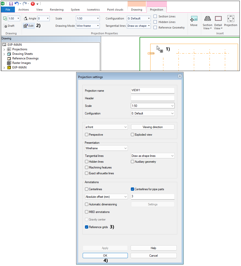
Activate the projection by clicking on it with the left mouse button, in picture 1).
-
Projection tab > Edit, in picture 2).
-
Projection settings window opens > Check/Uncheck the checkbox for Reference grids, in picture 3).
-
Close the window with the OK button, in picture 4).
-
-
Per Drawing
-
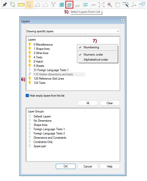
Ribbon > Select layers from list, in picture 5).
-
Hide layers 120 Reference Grid Lines and 124 Texts by turning off the light, in picture 6).
-
If your layer list does not show numbers and texts, right-click on the screen and activate the options Numbering and Numeric Order, in picture 7).
-
-
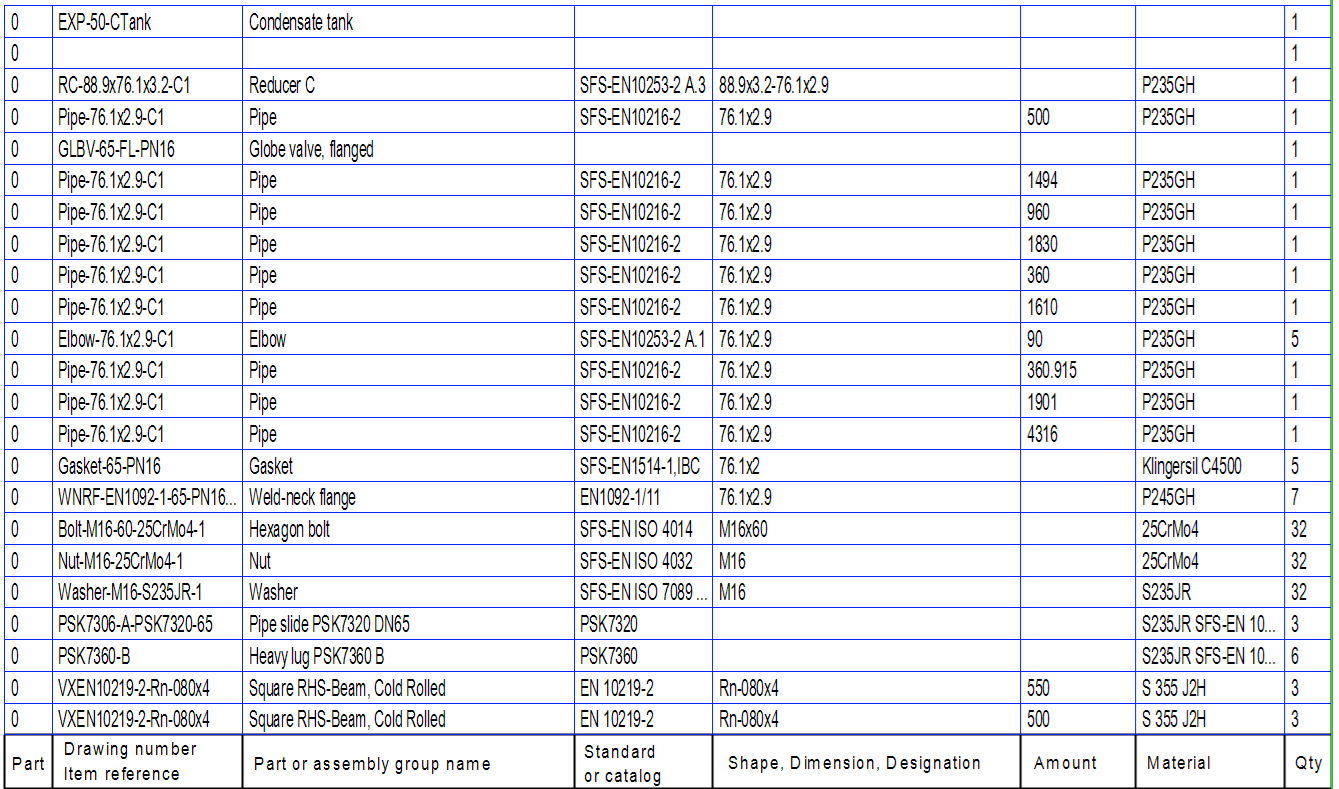
Drawing's parts list
-
You can find the data of pieces of the pipeline and equipment in the parts list.
-
You can delete the parts list if you don't need it:
-
Press the button Alt from your keyboard and keep it pressed > Click the parts list with the mouse left button.
-
You have now selected the parts list > Context-sensitive function: Delete (Del).
-
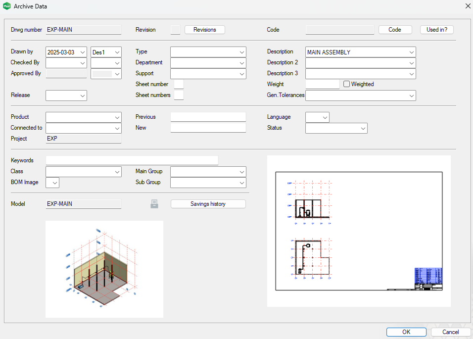
Check the archive data of the drawing and refresh the drawing
The drawing inherits the archive data from the model. You can modify the data.
-
Tab Archives > Data (when the drawing is active).
-
Fill and modify the archive data. More is better.
-
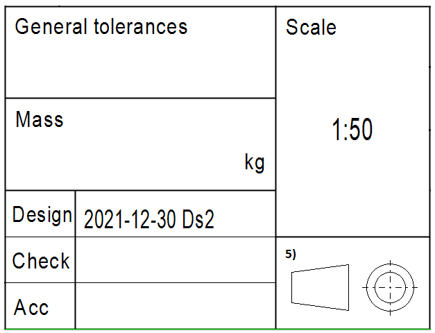
Some of the data fields are visible in the title block.
-
You can use the most of the data fields as searching parameters if you search drawings with the fucntion File > Open > Drawing.
-
-
Exit the archive data window by clicking the OK button. Then refresh the drawing by pressing the F5 button from your keyboard, which updates the title block and refreshes the drawing borders.
-
The drawing is now ready.
Save the drawing
-
File > Save or click


-
Close the drawing.
Save the model
-
Save the main assembly also: File > Save or click
Please note, that you have to save the model at least once after you have created the drawing. This action connects the drawing to the assembly tree.
If you forgot to save the model after creating the drawing, then the model and drawing can be found through the archive, but the Drawings section of the model feature tree does not recognize the drawing.
You can fix this by attaching an archived drawing to the model:
-
In the feature tree, click Drawings.
-
Right-click function: Attach Archived Drawing.
-
Search the drawing in the archive, e.g, under the History > Recent folder.
-
Double-click the drawing to select it.
You can download here the result of the exercise 8 (EXP.vxz).
(2 958 KB)
This transfer package will create a project EXP and insert models, drawing, and other files into the archive. This package contains all data from the exercises 1-8.
We don't recommend using this package if you already conducted the exercise by using the same labels for the project and models as guided.