Exercise 5: How to add supports
The main objective of this exercise is to add primary supports to the pipeline and secondary supports to support primaries.
The estimated time to complete this exercise is 10 minutes.
This exercise was carried out with Vertex G4Plant 31.0 (2025).
In this exercise, you will learn to
-
How to insert primary supports.
-
How to insert secondary supports.
-
How to set positions for supports.
Functions in use
-
Add primary support
-
Top View
-
Context-sensitive function: Constraints > Fix
-
Context-sensitive function: Exit
-
Insert variable secondary support
-
Context-sensitive function: Snap > Set local origin (Q)
-
Context-sensitive function: Constraint > Z axis (O)
-
Context-sensitive function: Dimension table
-
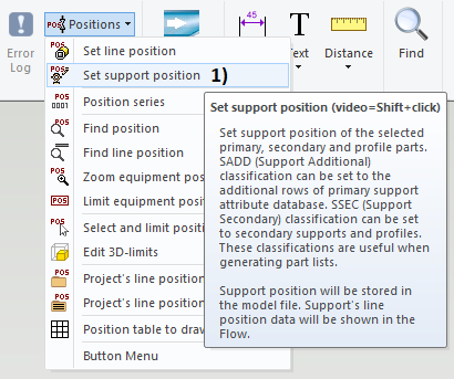
Positions > Set support position
-
Save
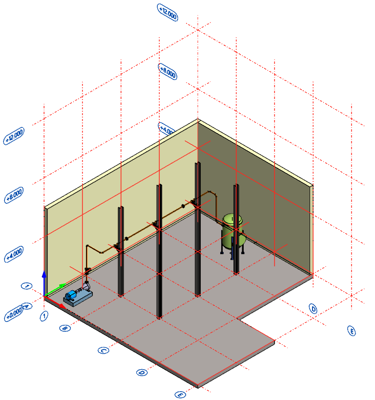
Open the model of your main assembly
-
Open the model of your main assembly (EXP-MAIN.vxm) from the previous exercise.
-
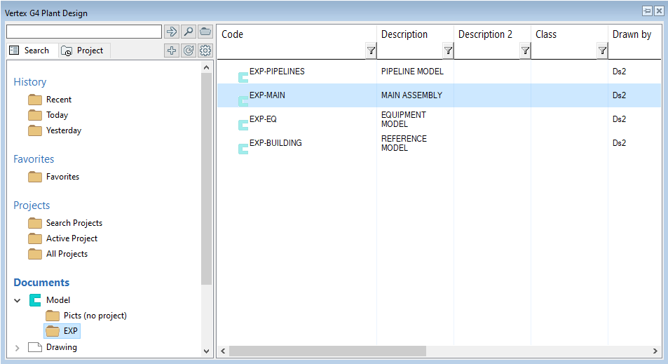
Open the basic browser by pressing B and find the segment Documents.
-
The segment Documents divides into two main branches Model and Drawing.
-
Search the folder of your project from the branch Model. Then double-click it to open the model.
-
You can find more information about the browser here.
Edit the pipe model
-
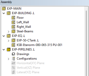
Select the pipe model (EXP-PIPELINES) from the assembly tree.
-
Context-sensitive function: Edit or double-click the sub-assembly from the assembly tree.
-
You are now at the editing state of the pipe model. You can see the symbols of other assemblies as unsharp in the tree. The symbol of the model you are editing is sharp in the tree.
Adding primary supports
Let's add three slide supports to the pipeline.
Selecting support type and defining the support data
-
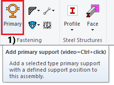
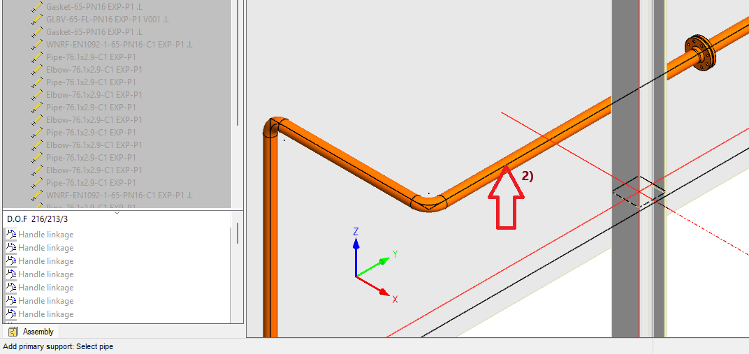
Function Add primary support, in picture 1).
-
Select pipe to which you want to add the primary support, in picture 2).
-
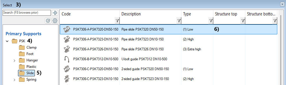
Window Select opens, in picture 3).
-
Select folder PSK and sub-folder Slide, in picture 4) and 5).
-
Select support PSK7306-A-PSK7320-DN50-150 by doubli-clicking the row, in picture 6).
-
Define the following specs for your support in tab Primary supports, in picture 7).
-
Määritä seuraavaksi primäärikannakkeen ominaisuudet Primäärikannakkeet-välilehdellä, kuvassa 7).
-
Some properties come automatically like nomina lsize and type.
-
Some property fields are related to hanger supports like load classification and cannot be selected.
-
Select attachment as Pipe slide, in picture 8).
-
Select lugs as Heavy lug PSK7360 B, 2 pcs, in picture 9).
-
Select stoppers as No stoppers, in picture 10).
-
Field Material gets value automatically, but you can change it if needed, in picture 11).
-
Clamp's installation angle is 0 degrees by default. You can chanke it if needed, in picture 12).
-
Type value S0001 for supports position or click plus symbol to get the position, in picture 13).
-
-
We place the supports in the next phase.

Placing primary supports to the pipeline
-
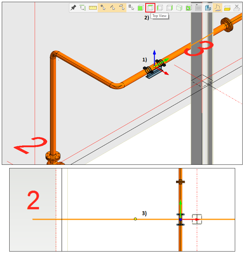
After the steps in the previous phase, the support now follows the centerline of the pipeline and movements of your mouse, in picture 1).
-
Click the button Top View from the tool strip, in picture 2).
-
Digitize the gridline 2 from the geometry, in picture 3) > The program adds the first primary support.
-
The function Add primary support is still active > Give the position S0002 like in a previous picture 13).
-
Digitize the gridline 3 > The program adds the second primary support.
-
The function Add primary support is still active > Give the position S0003 like in a previous picture 13).
-
Digitize the gridline 4 > The program adds the third primary support.
-
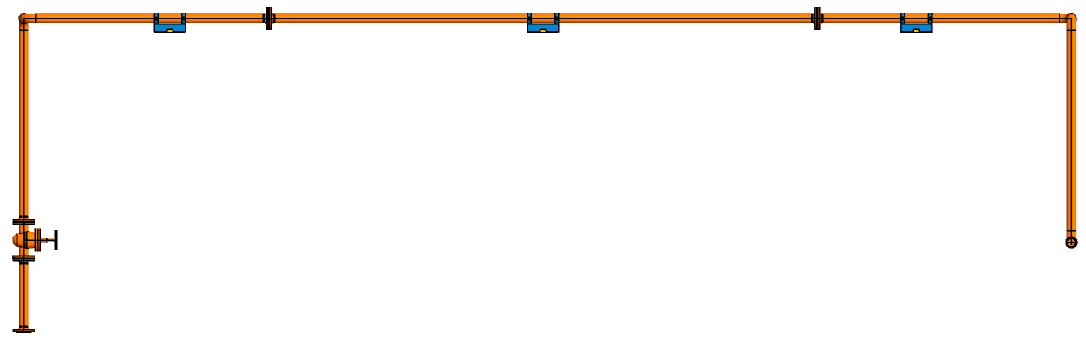
The third and last support is now in its place.
-
Context-sensitive function: Exit.
-
Select all three supports and all lugs from the model or tree (Ctrl + left mouse button) > Context-sensitive function: Constraints > Fix.
Adding secondary supports
Let's add three secondary supports into the pipeline.
Placing secondary supports to the assembly
-
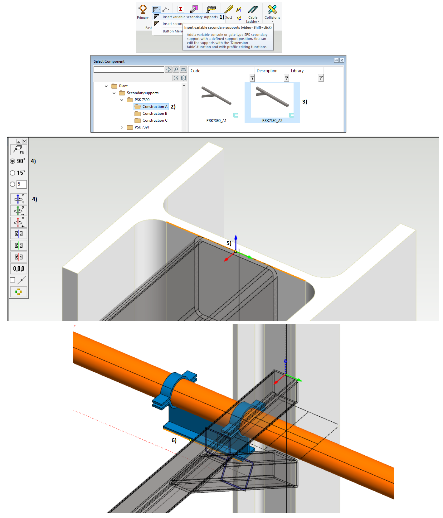
Function Insert variable secondary support, in picture 1).
-
Select the folder plant > Secondarysupports > PSK 7390 > Construction A, in picture 2).
-
Select the model PSK7390_A2 and double-click it, in picture 3).
-
Close the Dimension Table window by clicking OK.
-
The secondary support is now on tip of your cursor.
-
Rotate the support twice 90 degrees around the z-axis, in picture 4).
-
Rotate the assembly so that you can see the top of the beam at the intersection of gridlines 2 and B.
-
Move the cursor to the top of that specific beam and locate the middle point of the line like in picture 5).
-
Context-sensitive function: Snap > Set local origin (Q).
-
Context-sensitive function: Constraint > Z axis (O).
-
Select a point, line, or plane from the primary support's bottom, in picture 6).
-
The program inserts the first secondary support.
-
Repeat these steps to add two more secondary supports to the beams in intersections 3-B and 4-B.
-
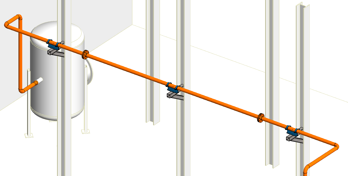
You will have three secondary supports in the assembly eventually.
Editing and fixing secondary supports
-
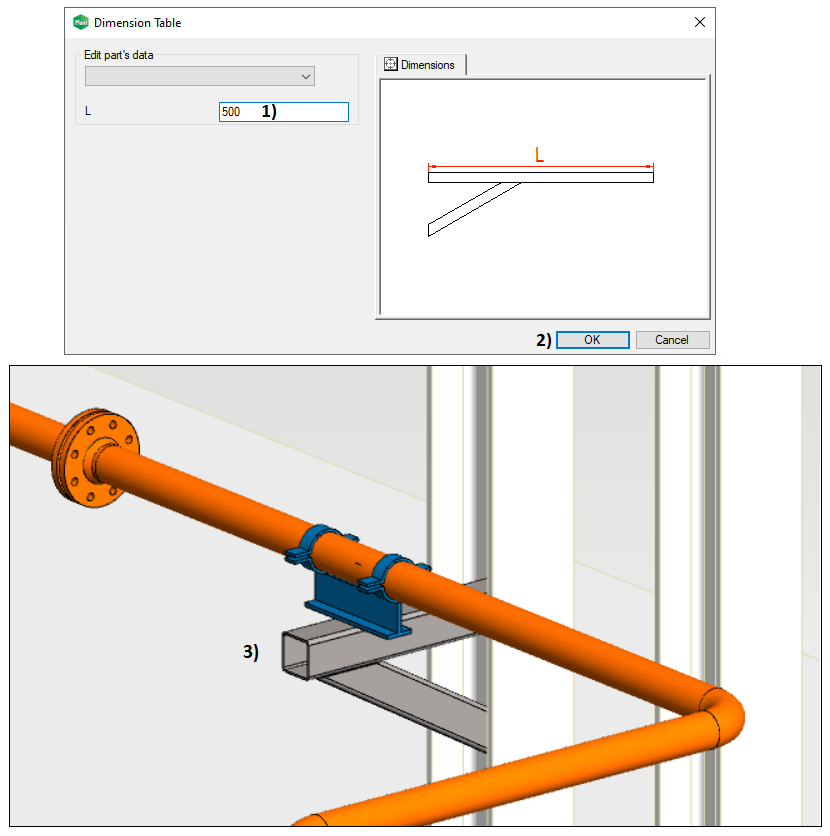
Select one of the secondary supports from the model or tree. Then double-click it or use the context-sensitive function: Dimension table.
-
Change the value L to 500 in the Dimension Table window, in picture 1).
-
Close the window by clicking the OK button, in picture 2).
-
The support's horizontal beam changes to match the value 500 mm, in picture 3).
-
Repeat these steps with two other secondary supports.
-
Select all three supports from the tree (Ctrl + left mouse button) > Context-sensitive function: Constraints > Fix.
Setting support positions
-
You can also set the position for primary supports with this technique. This is the main method to set the positions for secondary supports.
-
Function Positions > Set support position, in picture 1).
-
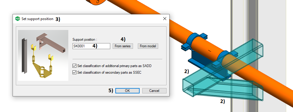
The next action is: Digitize parts of the support position. Digitize each part of the secondary support individually if it contains two or more parts, in picture 2).
-
Confirm the digitized parts > Context-sensitive function: OK.
-
The window Set support position opens, in picture 3) > Type Support position or use the function From series to generate the position, in picture 4) > Close the window by clicking the OK button, in picture 5).
-
Set position for all secondary supports.
-
Context-sensitive function: Exit.
-
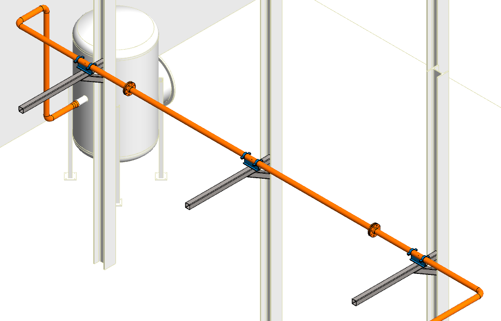
Supporting is now ready.
Save the model
-
Return to the main assembly level on the model > Working window > Right mouse button > OK. This action will save the changes of the sub-assembly to the archive.
-
Save the main assembly also: File > Save or click


You can download here the result of exercise 5 (EXP-PIPELINES.vxz). (585 KB)
This transfer package will create a project EXP and insert the model EXP-PIPELINES into the archive.
We don't recommend using this package if you already conducted the exercise by using the same labels for the project and models as guided.