Exercise 4: How to route a pipeline
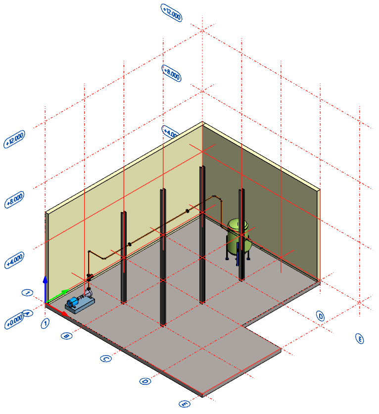
The main objective of this exercise is to route the pipeline from the pump to the vessel, add correct pipe components, and define the line position for the pipeline.
The estimated time to complete this exercise is 20 minutes.
This exercise was carried out with Vertex G4Plant 31.0 (2025).
In this exercise, you will learn to
-
How to route a pipe and use other routing tools while routing.
-
How to add pipe components to the line and equipment.
-
How to give a line position to the pipeline.
Functions in use
-
Add pipe component > Add reducer
-
Add pipe component > Add flange
-
Set line position
-
Add pipeline
-
Typing dimensions
-
Bolt length calculation
-
Context-sensitive function: Snap > Set local origin (Q)
-
Context-sensitive function: Constraint > X axis (U)
-
Context-sensitive function: Constraint > Y axis (I)
-
Context-sensitive function: Constraint > Z axis (O)
-
Context-sensitive function: Constraints > Fix
-
Context-sensitive function: Clipboard > Copy
-
Context-sensitive function: Clipboard > Paste
-
Context-sensitive function: Pipe system > Set line position
-
Save
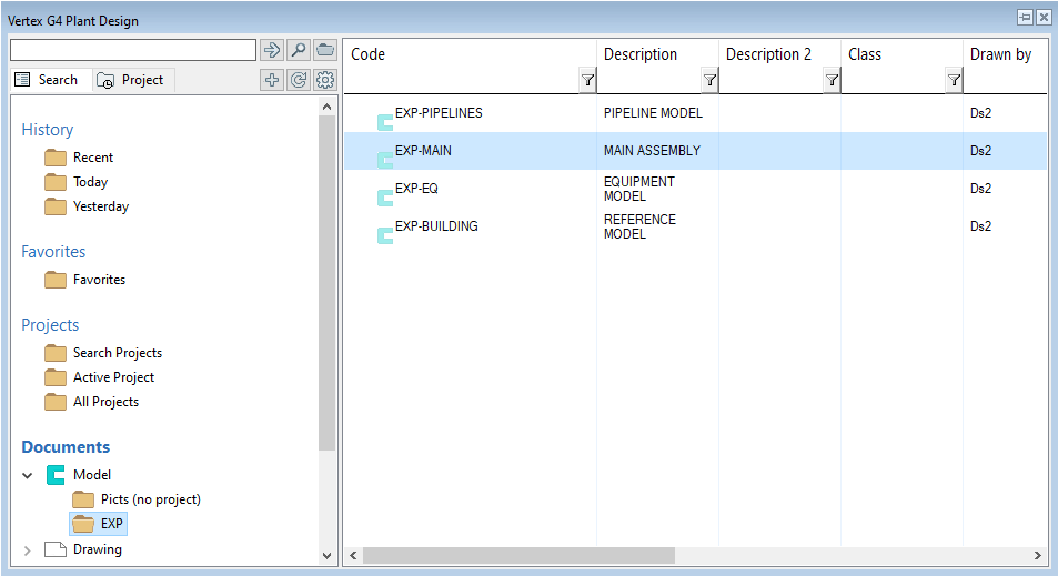
Open the model of your main assembly
-
Open the model of your main assembly (EXP-MAIN.vxm) from the previous exercise.
-
Open the basic browser by pressing B and find the segment Documents.
-
The segment Documents divides into two main branches Model and Drawing.
-
Search the folder of your project from the branch Model. Then double-click it to open the model.
-
You can find more information about the browser here.
Edit the pipe model
-
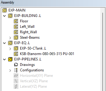
Select the pipe model (EXP-PIPELINES) from the assembly tree.
-
Context-sensitive function: Edit or double-click the sub-assembly from the assembly tree.
-
You are now at the editing state of the pipe model. You can see the symbols of other assemblies as unsharp in the tree. The symbol of the model you are editing is sharp in the tree.
The basics of Add pipe line function
-
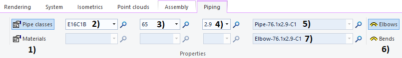
The function Add pipe line is located on the tab Assembly in the group Piping.
-
Properties of the pipe to be routed:
-
The pipe components are connected to each other with so-called pipe handles while you are routing the line and adding pipe components.
-
The starting point of the pipeline can be, for instance, the pipe handle or a reference point in the geometry.
-
You route the centerline of the pipeline from corner to corner. The program will fit the elbow or bend to the corner automatically by shortening the existing pipeline when the direction of the line changes.
-
You can find useful tools for routing from context-sensitive menus like Snap and Constraint.
-
Bunch of useful keyboard shortcuts:
The pipe end snaps automatically to the reference geometry while you are routing. You can define how fast or slow this reaction is.
-
File > User References > Drawings, Models.
-
Tab Usage > Common > Reference cursor Delay on Model (ms).
-
The default value is 3000.
The pipe components are connected to each other with so-called pipe handles (picture below) while you are routing the line and adding pipe components. You can define the size of the handles or hide them.
-
Resize the handles:
-
Context-sensitive function: Other functions > Resize Handles.
-
The default value is 50.
-
-
Hide and restore the handles:
-
File > User References > Drawings, Models.
-
Tab View > Model > Show Pipe Handles.
-
The check-box is enabled by default.
-
Routing the pipeline
-
Let's route the pipeline from the pump's discharge flange (DN 65) to the inlet (DN 80) of the vessel. Let's add all needed pipe components either while routing or after routing.
Adding a reducer to the vessel's inlet
-
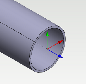
Let's start by adding a reducer to the vessel's (EXP-50-Ctank) orange inlet (DN 80). This specific inlet is on "the backside". There is another inlet on the side of the vessel, but its' nominal size is DN 65. Do not mix these two.
-
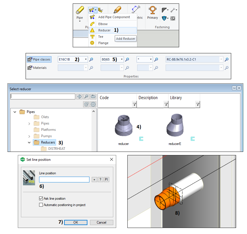
Function Add pipe component > Add Reducer, in picture 1).
-
Select the pipe class E16C1B (in picture 2)) and the nominal size (DN) 80.
-
Select the folder Reducers, in picture 3).
-
Select the pipe component reducer, in picture 4).
-
Select the size 80|65, in picture 5).
-
Select the pipe handle from the vessel's inlet and the program adds the reducer to its place.
-
Confirm the location and orientation of the component > Context-sensitive function: OK.
-
The program suggests a line position T001, NOZZLE-1 for the reducer. Clear the field and confirm the window by clicking the button OK, in picture 6) and 7).
-
The reducer is now in its place, in picture 8). Context-sensitive function: Exit.
Starting routing from the pump's discharge flange
-
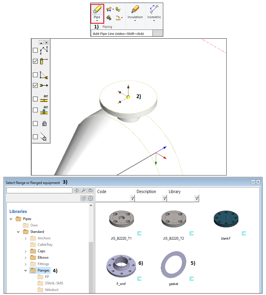
Function Add Pipe Line, in picture 1) > Select the pipe class E16C1B and the nominal size (DN) 65.
-
Note! It isn't necessary to change the nominal as the program recognizes the handle's nominal size and changes the DN size to match that value.
-
Select the pipe handle from the discharge flange of the pump KSB-Etanorm-080-065-315, in picture 2).
-
The window Select flange or flanged equipment opens as the program recognizes that it's now dealing with a flange connection, in picture 3).
-
Select the folder Flanges > Select the pipe component gasket, in picture 4) and 5). Double-click it.
-
The program adds the gasket to the pump's flange > Confirm the location and orientation of the component > Context-sensitive function: OK.
-
The window Set line position opens:
-
The window Select flange or flanged equipment opens again > Select the folder Flanges > Select the pipe component fl_wnrf and double-click it, in picture 4) and 6).
-
The program adds the flange to the gasket > Confirm the location and orientation of the component > Context-sensitive function: OK.
-
The next step is to route the pipe.
Routing the pipeline from the pump to a valve
-
The pipe centerline appears as a continuous line when you move the cursor up from the connection point.
-
The pipe centerline appears as a dashed line when you move the cursor down from the connection point.
-
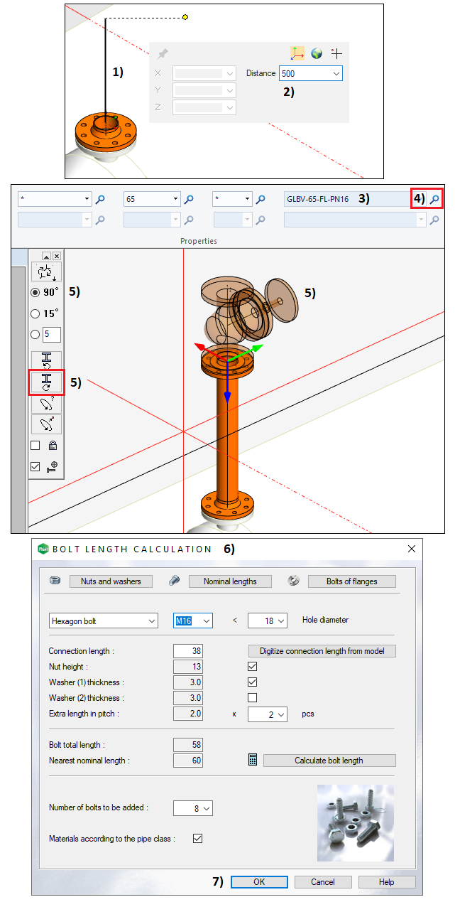
Move the cursor so that you see the continuous line, in picture 1).
-
Type the distance from your keyboard > Distance = 500, in picture 2) > Confirm the dimension by pressing Enter.
-
The program models the pipe segment after this action.
-
Let's add a flange to the pipe end > Function Add pipe component > Add Flange
-
Select the folder Flanges > Select the pipe component fl_wnrf and double-click it.
-
The program adds the flange > Confirm the location and orientation of the component > Context-sensitive function: OK.
-
Lets' add a gasket to the flange.
-
Select the folder Flanges > Select the pipe component gasket, in picture 4) and 5). Double-click it.
-
The program adds the gasket > Confirm the location and orientation of the component > Context-sensitive function: OK.
-
Let's add a globe valve to the gasket.
-
Select the folder Valves > Select the pipe component GlobeV_FL and double-click it.
-
Check that the valve item is GLBV-65-FL-PN16, in picture 3). If there is a different item, click the magnifying glass and select the correct item, in picture 4).
-
Rotate the valve right for 90 degrees. The axis of the handwheel should point to the direction of the y-axis, in picture 5).
-
Confirm the location and orientation of the component > Context-sensitive function: OK.
-
The program recognizes that you have created a flange pair and opens the window Bolt length calculation, in picture 6).
-
The program automatically calculates the distance between the bolt surfaces of the flanges and proposes suitable fasteners.
-
Close the window Bolt length calculation by clicking the button OK, in picture 7).
-
Add the gasket and flange to the other flange of the pump like you did earlier.
How to define an elevation for the pipeline
-
You can use the model's geometry in many ways while you are routing.
-
You should still have the function Add Pipe Line active.
-
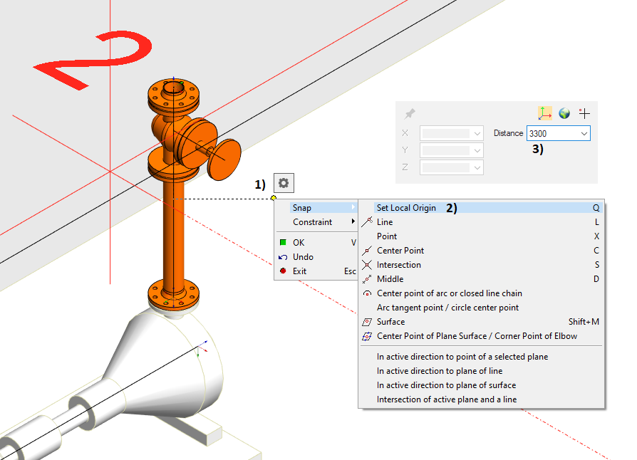
Move the cursor so that you can show the floor, in picture 1). You can see a symbol of a plane on the bottom right corner of the cursor's crosshair.
-
Context-sensitive function: Snap > Set local origin (Q), in picture 2).
-
Make sure that the pipe's centerline is above the floor's top surface > Type the dimension with your keyboard > Distance = 3300, in picture 3). > Confirm the dimension by pressing Enter.
-
The pipe end is now 3300 mm above the floor's top surface.
-
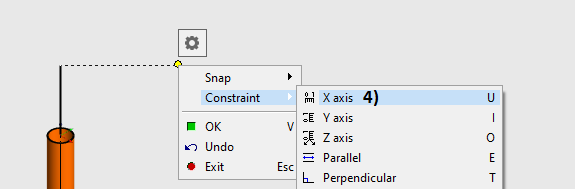
Context-sensitive function: Constraint > X axis (U), in picture 4).
-
Type the dimension with your keyboard > Distance = 1150 > Confirm the dimension by pressing Enter.
-
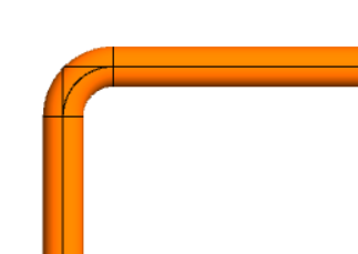
The program automatically adds an elbow between the straight pipe segments.
Route the pipeline to the vessel
-
Let's continue routing.
-
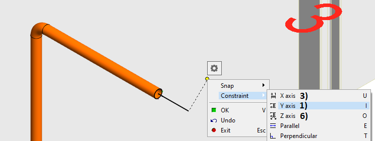
Context-sensitive function: Constraint > Y axis (I), in picture 1).
-
Move the cursor on the top of the reducer's pipe handle and click the left mouse button, in picture 2).
-
The pipe end is now level with the handle with an elevation of 3300 mm.
-
Context-sensitive function: Constraint > X axis (U), in picture 3).
-
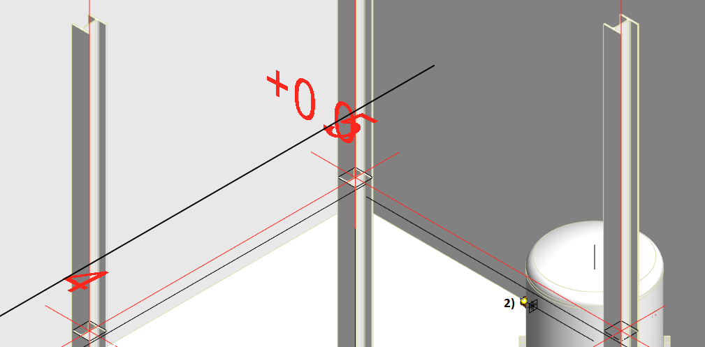
Move the cursor on the top of the gridline B, in picture 4) > Context-sensitive function: Snap > Set local origin (Q), in picture 5).
-
Make sure that the cursor is on the right side of the gridline B > Type the dimension with your keyboard > Distance = 250 > Confirm the dimension by pressing Enter.
-
Context-sensitive function: Constraint > Z axis (O), in picture 6).
-
Move the cursor on the top of the reducer's pipe handle and click the left mouse button.
-
Move the cursor again on the top of the reducer's pipe handle and click the left mouse button.
-
The pipeline is now at the "finish". You can close the routing function > Context-sensitive function: Exit.
Fixing the pipeline to its place
-
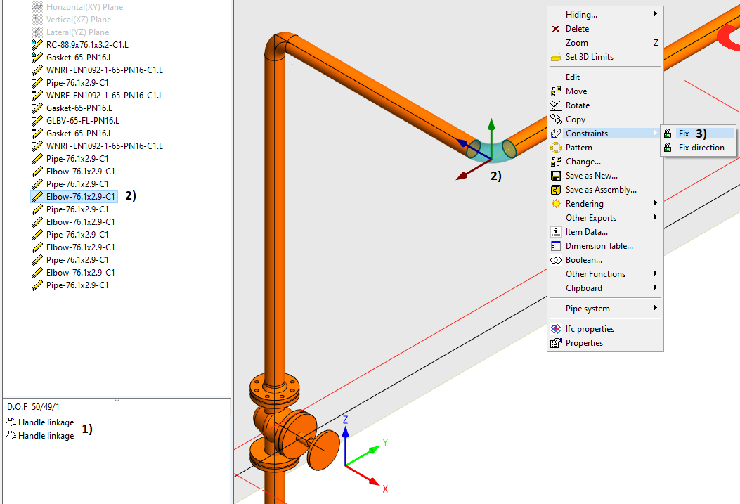
The pipe components automatically receive a constraint Handle linkage, in picture 1).
-
The handle linkages keep the pipe components attached, but they don't attach them to the surrounding geometry.
-
We recommended fixing a couple of the pivotal pipe components to their places.
-
Select from the model or tree one of the elbow which has the elevation 3300 mm, in picture 2) > Context-sensitive function: Constraints > Fix, in picture 3).
-
You can also fix other pipe components, for example, the valve.
How to add a flange connection to the line afterward
-
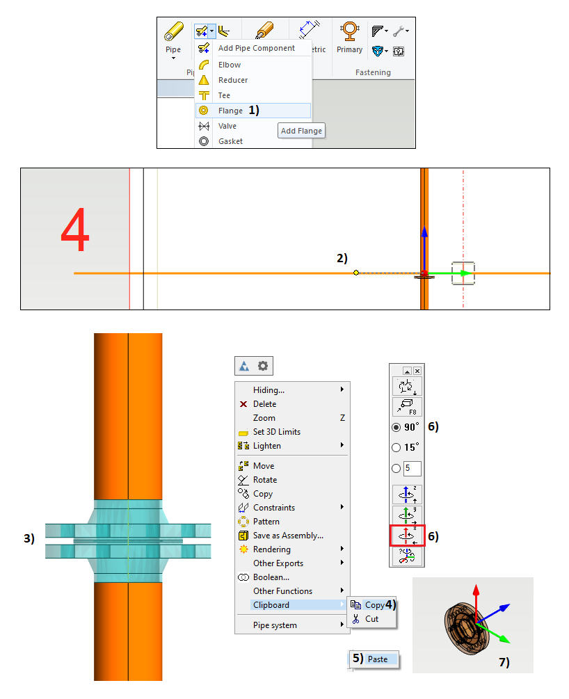
Function Add pipe component > Add flange, in picture 1).
-
Select the pipe class E16C1B and the nominal size (DN) 65.
-
Select the folder Flanges.
-
Select the pipe component fl_wnrf and double-click it.
-
The flange is now on tip of your cursor.
-
Move the cursor on the top of the pipe centerline and click the left mouse button.
-
The flange moves now along the centerline if you move the cursor.
-
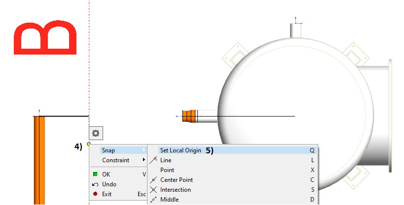
Move the cursor to the gridline 4, in picture 2) > Context-sensitive function: Snap > Set local origin (Q).
-
Move the cursor towards the pump and type the dimension with your keyboard > Distance = 750 > Confirm the dimension by pressing Enter.
-
Add the gasket, second flange, and fasteners.
-
Context-sensitive function: Exit.
-
The program splits the pipe into two segments after the flange pair is set to the pipeline.
How to add a flange connection to the line afterward via the clipboard
-
Select the newly added flanges and gasket from the model or tree, in picture 3).
-
Context-sensitive function: Clipboard > Copy, in picture 4).
-
Add the flange pair to the assembly > Context-sensitive function: Clipboard > Paste, in picture 5).
-
The flange pair is now on tip of your cursor.
-
Rotate the flange pair twice 90 degrees around the X-axis, in picture 6), if the flange pair is in your cursor like in picture 7).
-
Move the cursor on the top of the pipe centerline and click the left mouse button.
-
The flange moves now along the centerline if you move the cursor.
-
Move the cursor to the gridline 2, in picture 2) > Context-sensitive function: Snap > Set local origin (Q).
-
Move the cursor away from the pump and type the dimension with your keyboard > Distance = 750 > Confirm the dimension by pressing Enter.
-
Context-sensitive function: Exit.
-
The second pair of flanges is now in their place.
Set line position
-
Set a line position now if you didn't do it earlier.
-
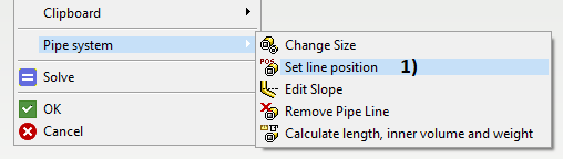
Context-sensitive function: Pipe system > Set line position, in picture 1).
-
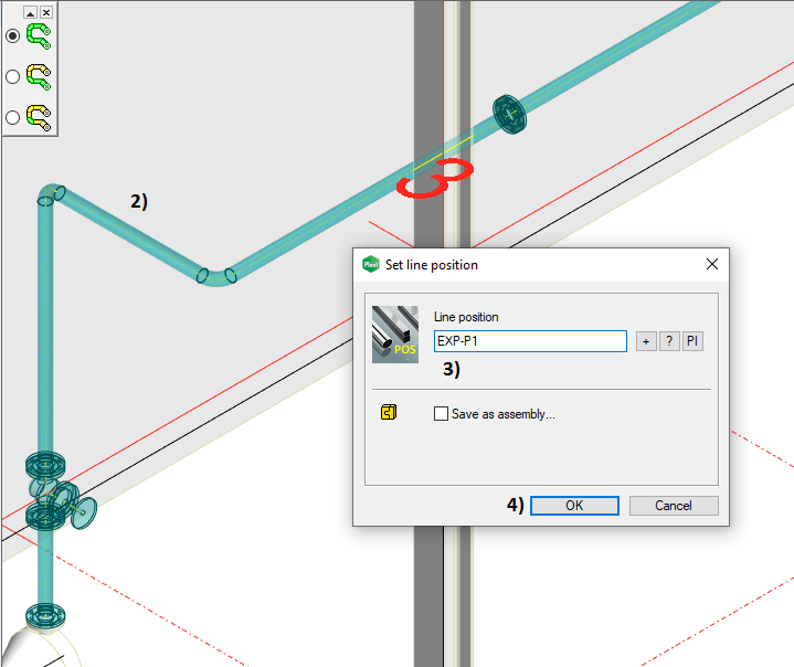
Select one of the pipe components from your line and the program highlights the line, in picture 2).
-
Type the line position EXP-P1 to the field and click the OK button, in picture 3) and 4).
-
Context-sensitive function: Exit.
-
The pipeline has now the position.
Set equipment position
-
The valve's position (equipment position) will be added to the isometric drawing.
-
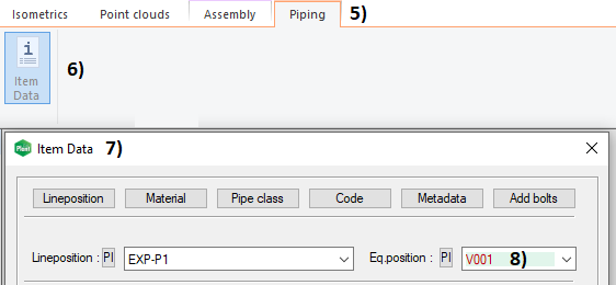
Select the valve from the model or tree > Tab Piping opens, in picture 5).
-
Function Item Data > The window Item Data opens, in picture 6) and 7).
-
Type the position V001 to the field Eq.position, in picture 8).
-
Close the window with the button OK.
Save the model
-
Return to the main assembly level on the model > Working window > Right mouse button > OK. This action will save the changes of the sub-assembly to the archive.
-
Save the main assembly also: File > Save or click


You can download here the result of exercise 4 (EXP-PIPELINES.vxz). (332 KB)
This transfer package will create a project EXP and insert the model EXP-PIPELINES into the archive.
We don't recommend using this package if you already conducted the exercise by using the same labels for the project and models as guided.