

Exercise 2: How to add reference models to the assembly
The main objective of this exercise is to add the reference grid to your building model and model the essential parts of the building itself.
The estimated time to complete this exercise is 25 minutes.
This exercise was carried out with Vertex G4Plant 31.0 (2025).
In this exercise, you will learn to
-
How to open an assembly from the browser
-
How to edit the sub-assembly
-
How to create the reference grid
-
How to insert and model a local part model
-
What component library offers for you
-
How to add a profile
Functions in use
-
Browser (B)
-
Context-sensitive function: Edit
-
Define reference grid
-
Context-sensitive function: New > Part
-
Sketch to face or line > To horizontal (XY) plane
-
Sketch: Polyline
-
Sketch: Dimensioning
-
Extrude
-
Context-sensitive function: Add > Component...
-
Rotate around the Z axis
-
Context-sensitive function: Constraints > Fix
-
Context-sensitive function: Properties
-
Context-sensitive function: Rendering > Change material...
-
Profile
-
Context-sensitive function: Snap >Intersection (S)
-
Context-sensitive function: Copy
-
Context-sensitive function: Save as assembly...
-
Save
Handling the main assembly
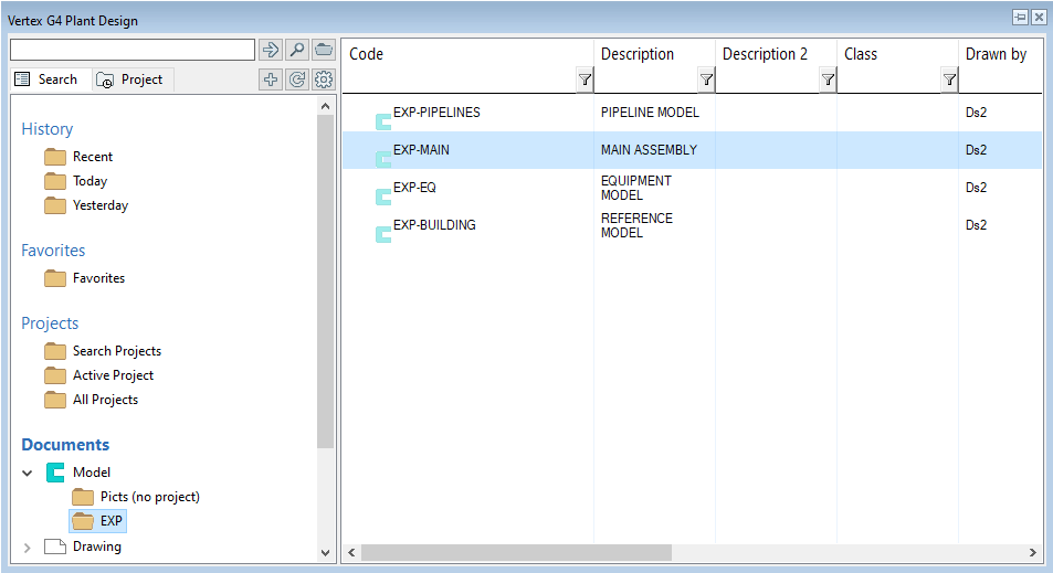
Open the model of your main assembly
-
Open the model of your main assembly (EXP-MAIN.vxm) from the previous exercise.
-
Open the basic browser by pressing B and find the segment Documents.
-
The segment Documents divides into two main branches Model and Drawing.
-
Search the folder of your project from the branch Model. Then double-click it to open the model.
-
You can find more information about the browser here.
Edit the building model
-
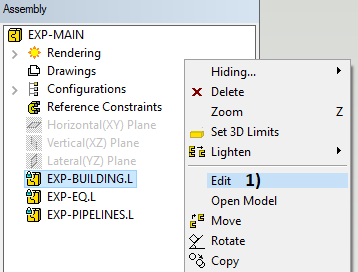
Select the building model (EXP-BUILDING) from the assembly tree.
-
Context-sensitive function: Edit or double-click the sub-assembly from the assembly tree, in picture 1).
-
You are now at the editing state of the building model. You can see the symbols of other assemblies as unsharp in the tree. The symbol of the model you are editing is sharp in the tree.
Add a reference grid
-
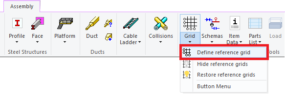
Tab Assembly > Select a function Define reference grid from the ribbon.
-
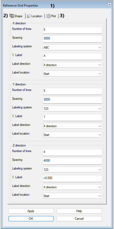
Window Reference Grid Properties opens, in picture 1).
-
Tab Shape > Define number of lines, spacing, labeling system, label direction and location, in picture 2).
-
X direction:
-
Number of lines: 5
-
Spacing: 3000
-
Labeling system: ABC
-
1. Label: A
-
Label direction: X direction
-
Label location: Start
-
-
Y direction:
-
Number of lines: 5
-
Spacing: 3000
-
Labeling system: 123
-
1. Label: 1
-
Label direction: X direction
-
Label location: Start
-
-
Z direction:
-
Number of lines: 4
-
Spacing: 4000
-
Labeling system: 123
-
1. Label: +0.000
-
Label direction: X direction
-
Label location: Start
-
-
Tab Plot > Define the styles of lines and labels, in picture 3). Change Height of labels to 200 and enable the check-box Add frame.
-
Approve by clicking OK button. The program plots the grid to the screen.
-
You can edit the existing grid either by starting the function again or selecting the object Reference grid from the assembly tree and then right mouse button and Edit.
Model the floor
Starting modeling a part and moving to sketch
-
Create a new local part to your building model:
-
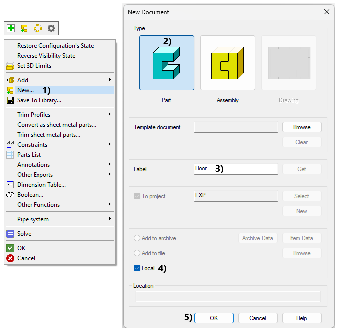
Context-sensitive function: New... in picture 1).
-
Select the document type as Part, in picture 2).
-
Type a label Floor to the part, in picture 3).
-
Enable the check-box Local, in picture 4).
-
Finally click OK, in picture 5).
-
-
You will now move to the part modeling state.
-
Ribbon: Start the function Sketch to face or line > To horizontal (XY) plane, in picture 6).
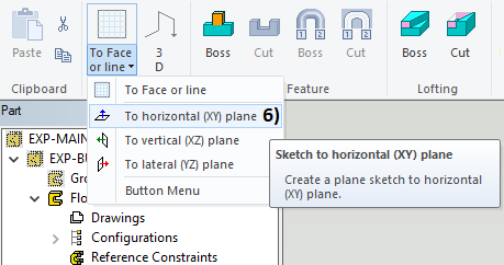
In the beginning, it may be easier to draw a sketch if the sketch plane is perpendicular to you.
-
You get a perpendicular sketch when you have selected Perpendicular in the Settings group on the ribbon.
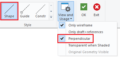
To draw a sketch, use the line style Shape.
-
Guide line is shown only in the sketch.
-
Construction line is shown as an auxiliary geometry, but it does not participate in the extrusion operation.
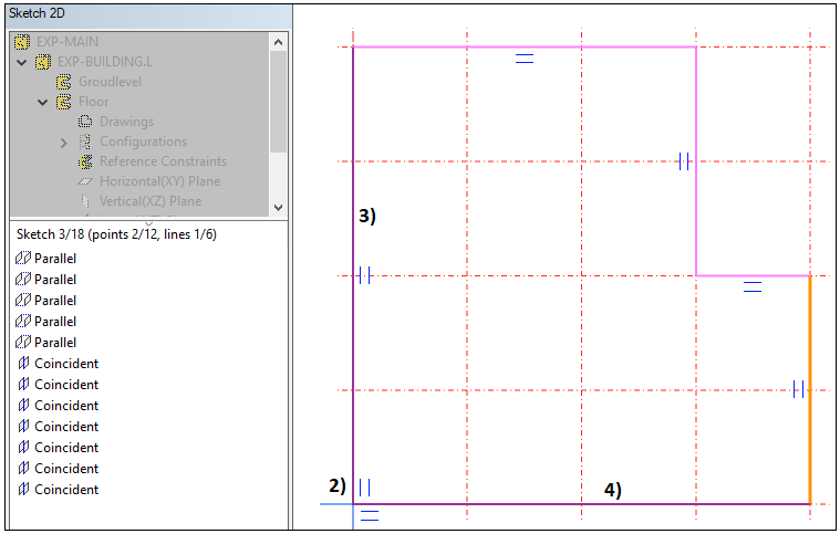
Sketch line chain
-
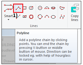
Use the function: Polyline, in picture 1).
-
Draw the line chain:
-
Select the sketch origin (blue cross) as the first point, in picture 2).
-
Start drawing the line chain upwards parallel to the y-axis, in picture 3).
-
Lock movement to the x-axis with the keyboard shortcut U.
-
Lock movement to the y-axis with the keyboard shortcut I.
-
-
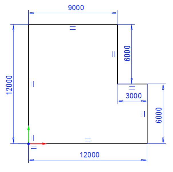
Please check the the final shape of the line chain from the picture on the right.
-
You can use the grid lines while drawing this line chain after locking the movent parallel to the main axis.
-
When you are sketching the lowest horizontal line, snap the end point to the origin, in picture 4) and 2).
-
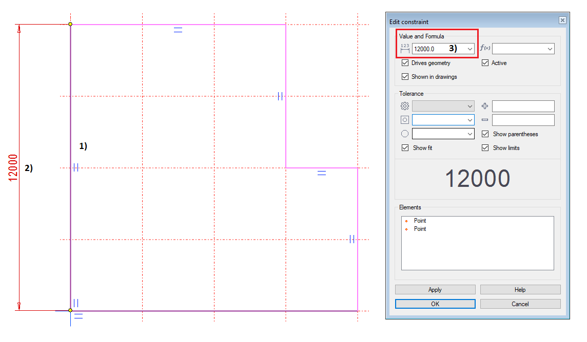
Dimensioning
-
Use the function: Dimensioning (Fast dimensioning).
-
Select the line to be dimensioned, in picture 1).
-
Select the location for dimension, in picture 2).
-
The program opens the window Edit dimensions.
-
-
Type the value 12000, in picture 3).
-
Approve by clicking OK.
-
Define the remaining lines according to the picture on the right.
-
Eventually, your sketch is fully defined.
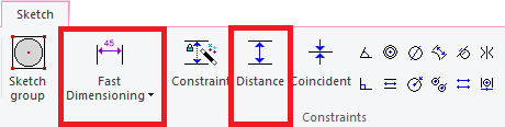
With the function Dimensioning (Fast dimensioning), you click a single line, which gives the length of a segment, the radius of an arc, or the diameter of a circle.
With the function Distance, you always click two elements (lines or points).
-
If you click two lines, the program also turns the lines parallel.
Extrude the sketch
-
Approve the sketch: OK.
-
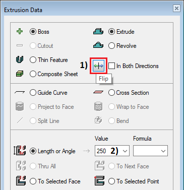
Change the extrusion direction (downwards from XY plane) by clicking the button Flip, in picture 1). Rotate the sketch for a better view, if needed.
-
Type the extrusion length 250 to the field Length or Angle, in picture 2).
-
Approve Extrusion data by clicking OK.
Return to the assembly mode: OK.
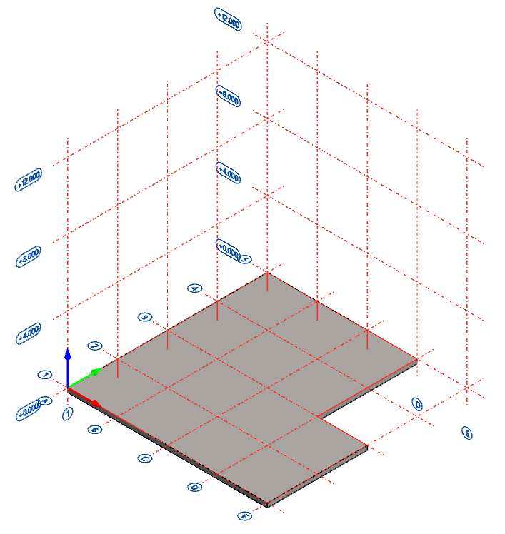
Your local Floor model is now ready.
Adding walls
Add the first wall to the assembly
-
Context-sensitive function: Add > Component...
-
Select the folder Basic_Shapes.
-
Select the component rectangle and double-click it.
-
Define the dimensions:
-
a = 12000
-
b = 250
-
h = 6000
-
Then OK.
-
-
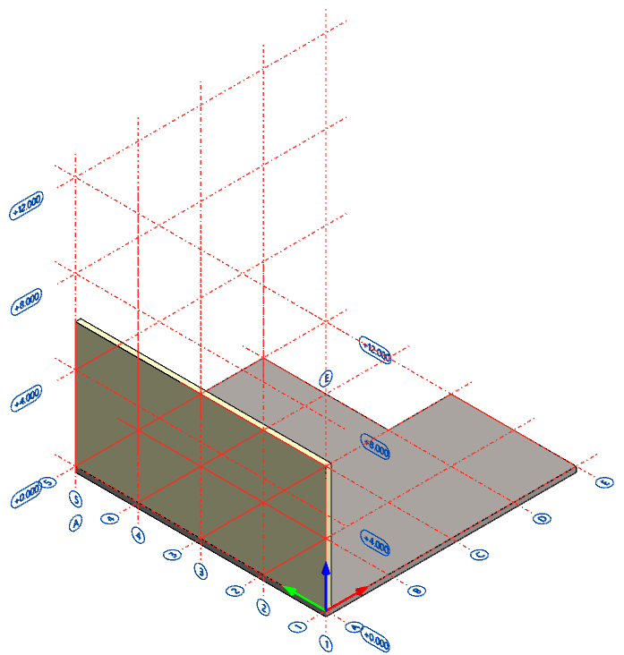
Place the wall element to assembly's origin. Be sure that the element is on top of the floor, like in the picture on the right.
-
Use these functions to help your task:
-
Rotate the wall element once 90 degrees


-
Change the reference point (F8)

-
Place the element to the assembly's origin either with the button

-
End the function: Esc from your keyboard or context-sensitive function: Esc.
-
-
Select the wall from the model window or assembly tree:
-
Context-sensitive function: Constraints > Fix.
-
Context-sensitive function: Properties.
-
Change Name from rectangle to Left_Wall.
-
OK.
-
-
Context-sensitive function: Rendering > Change material...
-
Browse.
-
Vertex Palette > VxColor_218 (double-click).
-
OK.
-
-
-
The left wall is now ready.
Add the second wall to the assembly
-
Context-sensitive function: Add > Component...
-
Select the folder Basic_Shapes.
-
Select the component rectangle and double-click it.
-
Define the dimensions:
-
a = 8750
-
b = 250
-
h = 6000
-
Then OK.
-
-
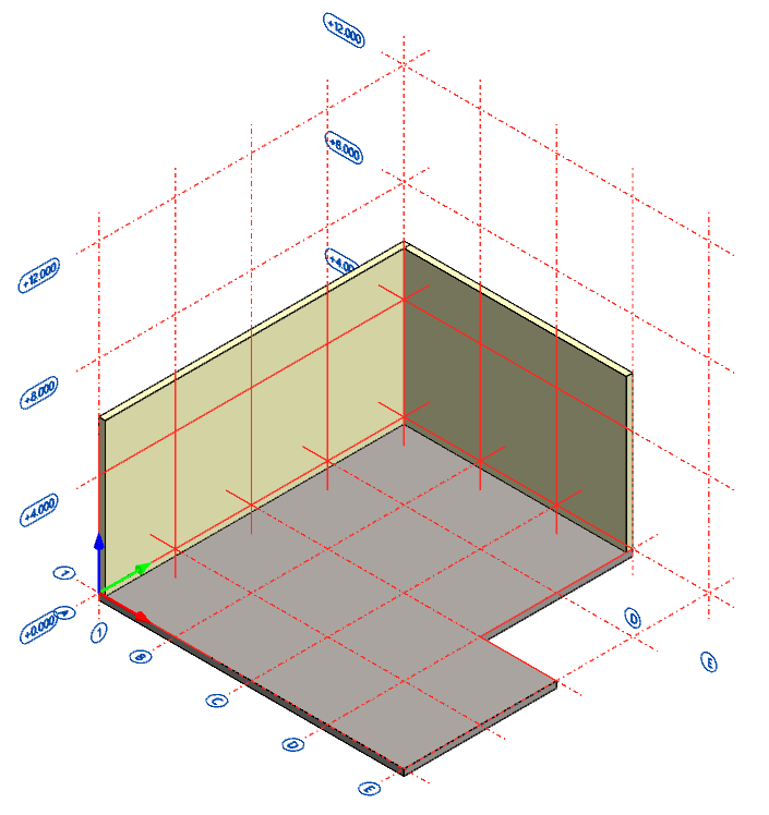
Place the wall element to assembly, like in the picture on the right. Be sure that the element is on top of the floor.
-
Rotate the wall element twice 90 degrees
-
Select the corner of the floor and place the second wall element to that point.
-
End the function: Esc from your keyboard or context-sensitive function: Esc.
-
-
Select the wall from the model window or assembly tree:
-
Context-sensitive function: Constraints > Fix.
-
Context-sensitive function: Properties.
-
Change Name from rectangle to Right_Wall.
-
OK.
-
-
Context-sensitive function: Rendering > Change material...
-
Browse.
-
Vertex Palette > VxColor_218 (double-click).
-
OK.
-
-
-
The right wall is now ready.
Add profiles to the assembly
-
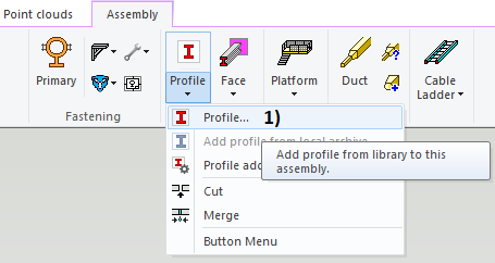
Use the function: Profile, in picture 1).
-
Select the folder Hotrolled.
-
Select the component DIN_1025-HEB and double-click it.
-
Select the size DIN1025-HEB200.
-
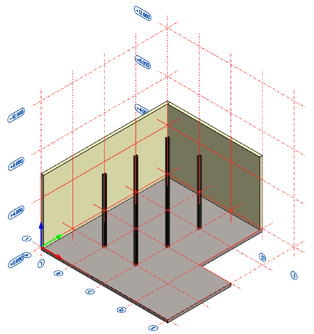
Move the cursor, where the profile's cross-section is now visible, to the intersection of gridlines 2 and B.
-
Context-sensitive function: Snap > Intersection (S).
-
The profile automatically locks itself on the z-axis according to the surface normal.
-
Route 6000 mm.
-
Add profiles to the intersections 3-B, 4-B, 2-C, 3-C, and 4-C.
-
Select all six profiles from the model or assembly tree > Context-sensitive function: Save as assembly... > Type a label Steel-Beams and enable the check-box Local.
-
The building model is now ready.
Save the model
-
Return to the main assembly level on the model > Working window > Right mouse button > OK. This action will save the changes of the sub-assembly to the archive.
-
Save the main assembly also: File > Save or click


You can download here the result of exercise 2 (EXP-BUILDING.vxz). (236 KB)
This transfer package will create a project EXP and insert the building model and the models from the exercise 1 into the archive.
We don't recommend using this package if you already conducted the exercise by using the same labels for the project and models as guided.