Position sketches and auxiliary planes using constraints
Position auxiliary planes and sketches using constraints.
Previously, sketches and auxiliary planes were positioned by assigning a transformation matrix, including translation and rotation as numerical values. This could cause positioning issues, especially with variable parts. These problems can be avoided by positioning sketches and auxiliary planes using constraints. You now have access to the same constraints as in the 3D sketching tool.
Positioning Auxiliary Planes
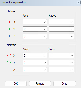
The old positioning dialog, where the transformation must be calculated numerically, is still available. You can access it by selecting an auxiliary plane or sketch and choosing "Move" from the right-click menu.
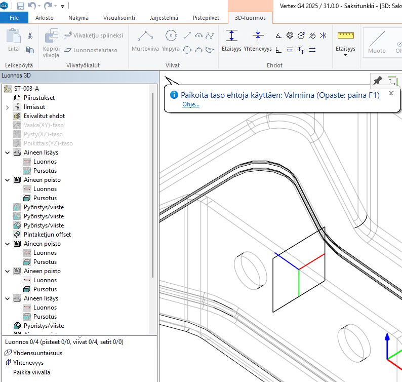
To use the new positioning method, select an auxiliary plane or sketch and choose "Position". The auxiliary or sketch plane will then appear as a reference in the geometry, allowing you to position it using constraints. This ensures that the planes automatically adjust to the correct orientation as the part's dimensions change. Previously, rotations had to be defined with formulas and calculated manually for each case.