Cutting the projection connection creates groups of the part lines
In some cases, you want to cut the connection between a projection of the drawing and the 3D model and continue drawing manually. In this case, it may be necessary to remove the geometry of some parts.
-
Now it’s easy because the drawing geometry of each part forms its own group.
-
Previously, the Cut Connection function created only single lines, making it more laborious to remove the geometry of overlapping parts.
After cutting the connection, you can select the groups one by one or by limiting an area and delete the selected geometry.
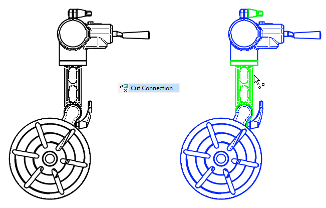
This feature was already introduced in version 27.0.03 (February 2021).
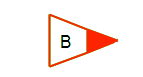
Add a revision mark to the drawing
The revision mark is used in the drawing to indicate the changed point so that the change can be easily seen from the drawing.
The symbol can be found in the folder: Symbols/Sheets (Symbols/Standard/Sheets)
-
The revision mark automatically retrieves the last change in the drawing in question in the change database (d_PIC_REV).
-
If you want to add another ID, extract the symbol and edit the ID text.
-
The revision mark scales to the scale at the time the drawing was added, but does not scale again if the drawing is scaled later. In this case, scaling must be done using the function Move groups.
Note that the revision mark does not appear in the cursor when you point to the mark position.
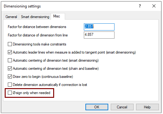
The diameter mark now always comes along the circle
The drawing practice has changed with the revision of the standard SFS-EN ISO 128 and nowadays the diameter mark is required in front of the dimension, even if it is an obvious circle. This default setting takes effect in version 28.0.00
-
If the user wants to deviate from the standard and continue dimensioning in the old style, then he/she can do so by changing the setting.
-
Drawins ribbon > Dimensions group > Dimension > Settings > Misc.
-
Select the line "Ø-sign only when needed" if you do not want the Ø sign to be added to the dimensioning of the circle.
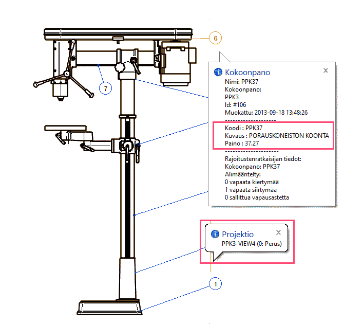
Tip text now shows more information than before
The tip text on the cursor tells you a projection name when taken on top of the projection borderline and part data, when placen on top of BOM marker. identifying parts is now easier than before. (Vertex ID: MEC-7346).