Manage Part Numbers in Assemblies
Part numbering in large assemblies is now possible in 3D -model
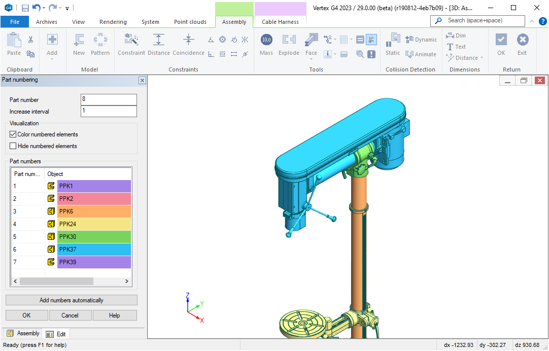
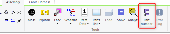
Function Add part numbers opens a dialog, which allows you to number the parts.
-
The program marks the numbered parts to assembly visually
-
You can also use automatic numbering
-
Double-click of the part number row opens the item data to be edited
Click on "Add part number" to open a dialog which lets you number the parts either automatically or manually
Create Design Automation Systems Easily Using Revised Dimension Table
Change Dimensions
New dimension table was introduced already in version 2022. This part of the functionality has not been changed.
Please note that only asselmby constraints and dimensions from local parts are coming to the dimension table. Local parts are easy to recognise from the fact that they do not have teh ".L" -extension in the part name.
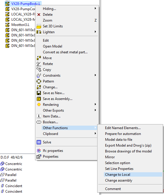
If yo uwant to make a lined part local, selct the part from the tree and click "Other functions" → "Change to local"
Change components based on the dimension set
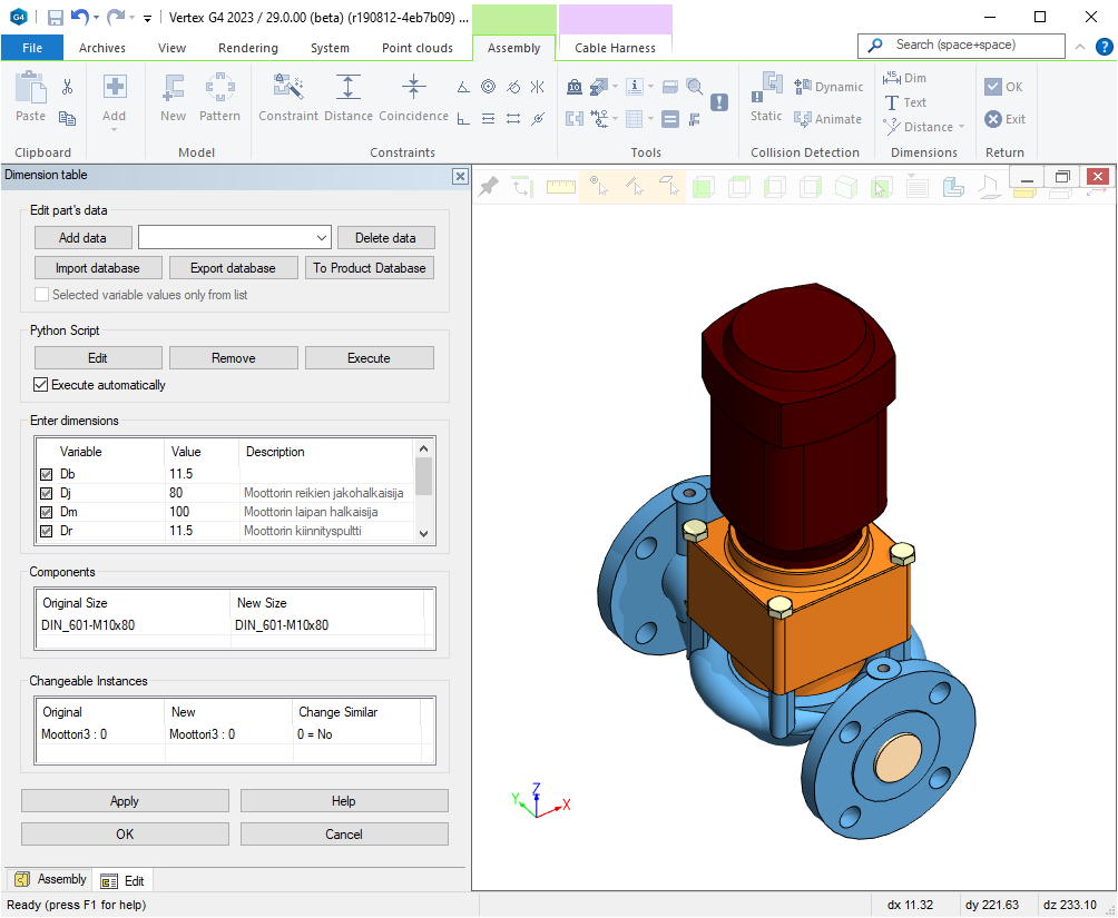
If there are components in the assembly, their dimesnions sets are visible in dimension table in the section "Components".
You can easily change all components from the dimenstion table without having to do that individually for every component
Using components with Flow
When Flow is used, you can change the items to different sizes based on them haveing the same connecte model obejct. If they hae, the item if considered interchangable.
Interchangable components are constrined automatically
Within the same product family you should conder using same named elements (surfaces, lines or points) or using predefined constraints.
If original assembly is built by constaringing the parts using the methods above, the constraints are connected, when ever the new part is changed.
Create a product family for interchangable parts
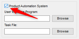
First select "Product Automation System" from assembly properties. Theis brings the extended features available for you.
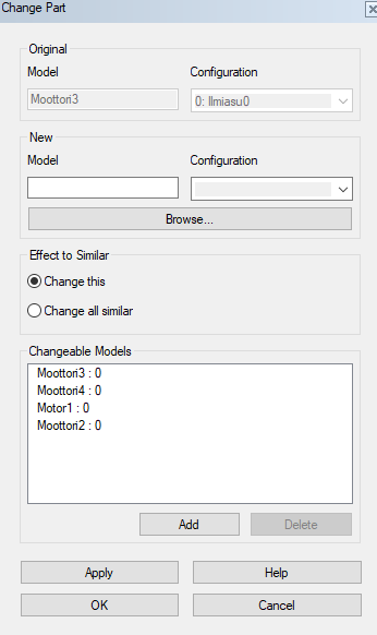
After this the "Change" -dialog will have a section named "Changable Models". You can search and add changable model to the list.
Next, in the dimension table you will see "Changable instances", where the listed parts and assemblies will be shown.
Use Python-program to Manipulate Dimension Table
What can you do with a Python -program?
Python is an object-oriented programming language (www.python.org) which you need to install to your own desktop computer. without Python intgerpreter your model will works just like a normal parametric model.
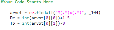
In the example above there is a function which changes the motor bed thickness and bolt hole dimensions according to the selected bolts. This was some sintelligence has been added to the model, the user doesn't have to remember to change all values.
You can also change parts and component sizes from the Python-program.
Naturally all the libraries of the Pythohn framework are at your disposal.
Creating a Python language program to the dimension table
There is a new seciton for the program. Edit/Create -button opens the program to be edited. You can change dimensions and parts in the program
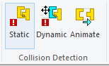
You Can Now Exclude a Part From Collision Detection
So far both static and dynamic collision detection have been takin all parts into consideration. However, somtime certain parts are allowed to go inside each other. Typically bolts nad nuts, and threads a colliding volume-wise. Also in certain cases a guide geometry is necerray to exclude from the collision detection.
There is now a chcekcbox in the part (To collision detection) with which you can affect if the part is taken into account in the collision detection.
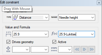
Animate Assemblies with Constraints
Creating an animation
All assembly constraints with a value can be used as an animation constraint. Constrinats will be executed in aplphabetical order, so the best thing to do is to use numbering in the constraint names.
Simply give the constraint a minimum and maximum value and if you prefer, in how many steps the animation will be done. THis affects the animation speed.
Performing the animation
Function starts when clicking a toolbar button "Animate".
This also works with dynamic collision detection. If the parts collide, animation stops. This way you can determine if your construction works how you wanted it to work.
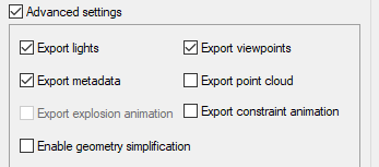
Showroom-support
While exporting to Showroom you can say is the constraint animation taken also.
Define Component Dimensions While Adding to Assembly
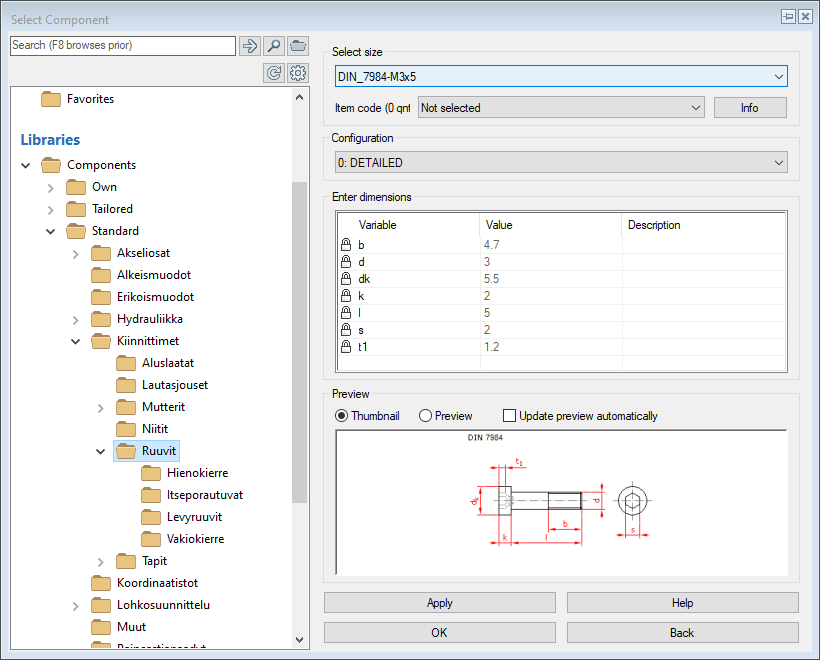
You can now select the dimension set, when adding a component from the browser. If the correct size/compoents is not found, you can easily click "Back" -button and go to another component. No need for closing the browser anymore!.
You can also digitize a dimension from the model using the right mouse button. Also for certain components you can select a specific size based on eg. diameter. Components like these are seger-rings.
Several Speed Improvements for Large Assemblies
We have done a lot of improvement for handling of the large assemblies.
Digitizing and geometry selection speed is improved. You can now digitize without delay
Selecing parts from the model has been completely re-written. In large models the digitizing is many times faster than before.
Createing STEP -models out of large assemblies is faster
When createing STEP- models Vertex G4 utilizes all availble processor cores for exporting.
Accurate section views from assembly drawings are faster than before
If section view is set to accurate, Vertex can now use all available processor cores to make sections for each part.
Degrees of Freedom are now calculated for large assemblies
When aaembly has enough parts, Vertex G4 automatically dstops showing the degrees of freedo fro individual parts.
Reading and updating an asselmbly from Flow is several times faster thatn before
Model is read from Flow to the local workspace is much faster than before. The larger the assembly, the bigger the time save. In 1,8GB model we got 8 times faster performance than in version 2022.
Tools needed for Imported Models Can Be Found in Their Own Tab
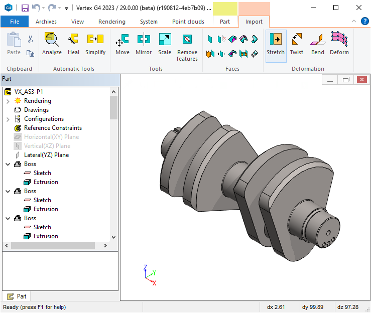
Imported models can cause problems, because odiffernet modelling platforms handle the geometry differently. Especially broken geometry parts tend to cause slowness and unreliability when used in assemblies. There is now a tab for imported parts, where we have collected all needed fnctins to fix, and manipulate imported geometry.
Automatic tools -group contain tools to analye and fix the imported models. Usually the part can be made whole by using only these tools.
Tools -group contians functions to manipulate the geometry of imported models.
Surfaces -tools allow you to go into more detail int o the surfaces of the models and repair the model manually by changin nad creating surfaces.
Modelling -tools allow you to manipulate (stretch, convert) the imported model without using feature based functions
Inspect Model Analysis Results Easier Than Before
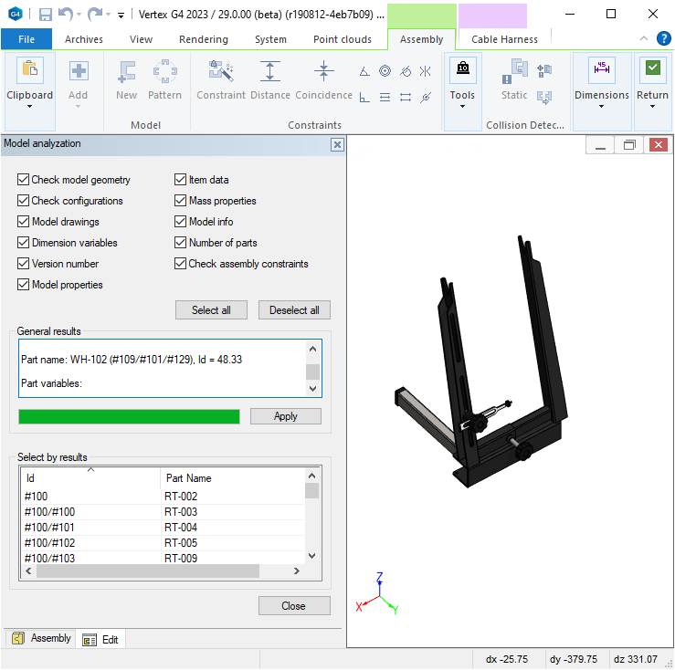
Version 2022 introduced a new tool for analyzing the model. Using this tool you can check the geometry health, assembly constints and many other properties of the model.
Version 2023 takes the tool even further. Analysis itself works as before, but usability has been improved a lot. Earlier it was difficult to find the correct information from the analysis results.
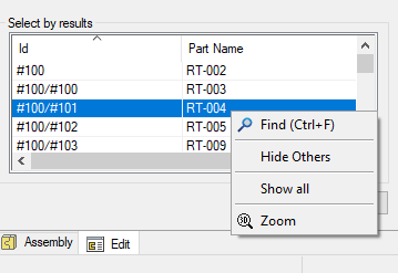
Now there is a reuslt list in the botttom of the dialog, from where you can search for the faulty part, fix problems related to it or locate the part from the model. When you select the part fro the list, the part is also selected from the model. Context sentive menu in the dialog also allows you to hide other parts or zoom into it.
Keep Geometry Healthy
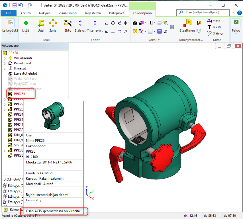
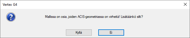
When importing models, the broken ACIS -geometry often causes problems and slowness. From verison 29 onwards he model is checked while importing or when analysis is done. After theis the ACIS-faulty parts are marked with red text in the assebly tree. When a fault part is addded into the assembly, a warning will be shown.
When the model is fixed, and analysis is done to prove the ACIS -errors are gone, the part is marked healthy, and it will work normally.
Program marks the faulty imported models with red text, and tip-window shows the notification.
The final models should never have any broken parts.