


Use constraints based on artificial intelligence
Add constraints guided by artificial intelligence
The function Add intelligent constraint is based on an artificial intelligence application that has analyzed a large number of constraints provided by users. The program first adds the most suitable constraint between the assigned element pairs and allows the constraint to be changed for another constraint.
-
So far, there is no artificial intelligence that follows the user's actions and learns from them in their own ways.
The files required for the AI feature are located in the MachineLearning folder under the system/programs64 folder.
-
This folder takes up about 1GB of disk space.
-
If necessary, the folder can be deleted, in which case artificial intelligence is disabled. Still, the Add intelligent constraint works, but without AI control.
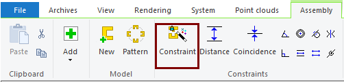
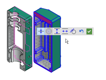
Start the function Add intelligent constraint and click on an element (face, line or point) from two different parts. The program sets the most suitable constraint used between these and allows the user to change the constraint to another.
In the figure below, the designer has clicked two planar faces between which the program has set a Coincidence constraint. At the same time, a menu opens from which the user can change the constraint to, for example, a Distance or Parallel constraint.
-
Note that in the example figure, the concentricity constraint is inactive (darker gray button) because it is not possible for planar faces.
Hide part or parts when you add constraints
When adding constraints a situation may arise where a part should be hidden so that a face, line, or point can be clicked from the part behind it.
-
Remember that this can be done by hovering over the part and pressing the

-
This old functionality also works when adding AI constraints.
Restore hidden parts while adding constraints.
You can restore all hidden parts in the middle of a function with a key combination 

Note, that this restores the hiding of all parts in the model, and not, for example, models that are restored by function: Restore Configuration's State.
-
This feature is useful when you are working on a model that does not have configuration based hidden modes, and by default, all parts are visible when you add constraints.
Assembly handling
Convert an imported part to an assembly
If an imported part (for example, a Step model) contains several volumes, you can convert it to an assembly model.
-
Right click function: Edit Model > Convert part to assembly.
The feature was already introduced in version 27.0.07 in May 2020.
A Step model contains information on whether it is a part or assembly model.
-
When a Step model is imported, the program does not ask if the model is to be read as part or assembly.
-
The model is read as part or assembly based on the information included in the Step file.
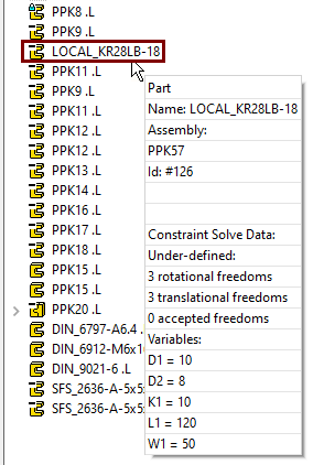
See variables related to the local part with their values
In the feature tree, you can view the variables associated with the local part and their values when you move the cursor over the local part.
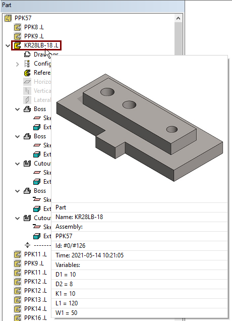
See the formulas related to the part when editing the part.
The feature tree does not directly show the formulas in the link part. To view the formulas in the link part, edit the part and move the cursor over the part symbol.
Change several parts at once to local parts
You can select multiple parts and subassemblies and switch them to local instances at the same time.
-
Select parts.
-
Right-click function: Other function > Change to local.
-
Select the number of parts to replace locally: First-level parts or all parts of the assembly recursively.
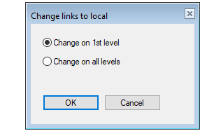
This feature can be used if you want to "freeze" a design situation so that its parts and subassemblies do not change later.
-
Save the assembly as a new one before you change its parts and subassembly to local.
-
Use Ctrl A to select all parts in the main level of the asembly.
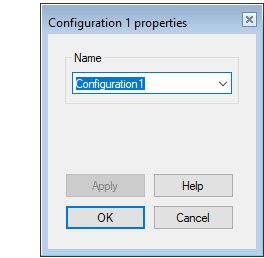
Name the configuration as you create it
When you create a new configuration, the program opens the Properties of X feature, so you can immediately rename the configuration.
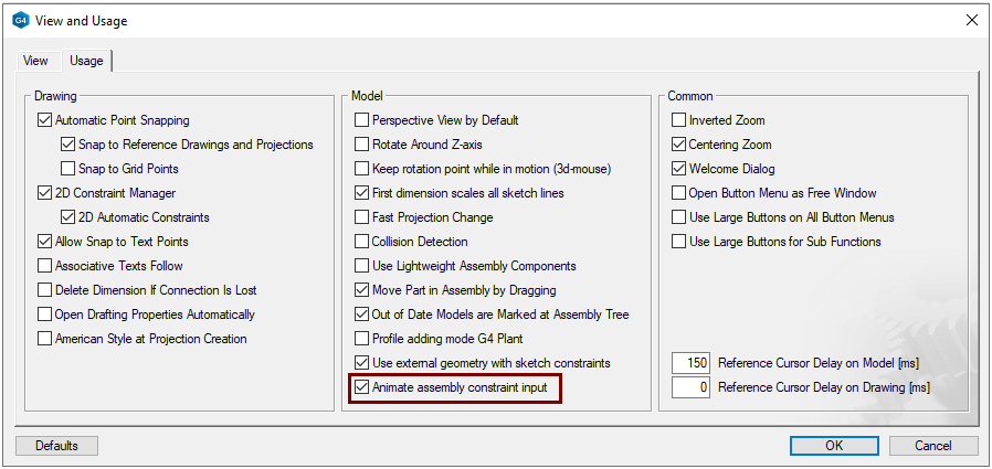
Use animated parts movements when add constraints
The parts slide animatedly into place (for 0.3 seconds). However, if you want the parts to snap into place quickly instead of animating, deselect the setting:
-
File > User Preferences > Drawing, Models > Usage-tab > Model-group > Animate assembly constraint input.
The Add Component dialog has changed
-
At the top you can select the dimension table row.
-
The program presents the variables, their value and description, if any.
-
The Item code and entry of Info is only possible if rows are stored in the dimension table.
-
At the beginning of the row of locked variables is a symbol of the lock.
-
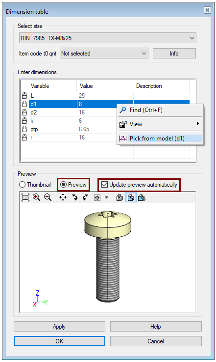
In any row, you can perform a measurement of the model with the right-click function: Pick from model.
-
Point the model to either a cylindrical face or two points.
-
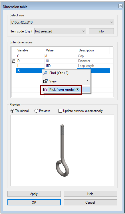
If you pointing a value to a locked variable:
-
The program looks for a row in the dimension table where the value of that variable matches.
-
If a row is found, it is automatically selected (and the values in the table are updated).
-
If more than one row was found, look at the other variables in the table and select the row with the most hits to the other variables.
-
If no rows were found, the user is notified and nothing is done.
If you assign a value to a free variable:
-
The value of the variable is changed to a table.
-
Select a row in the dimension table where the values of all variables match the values in the table (rare).
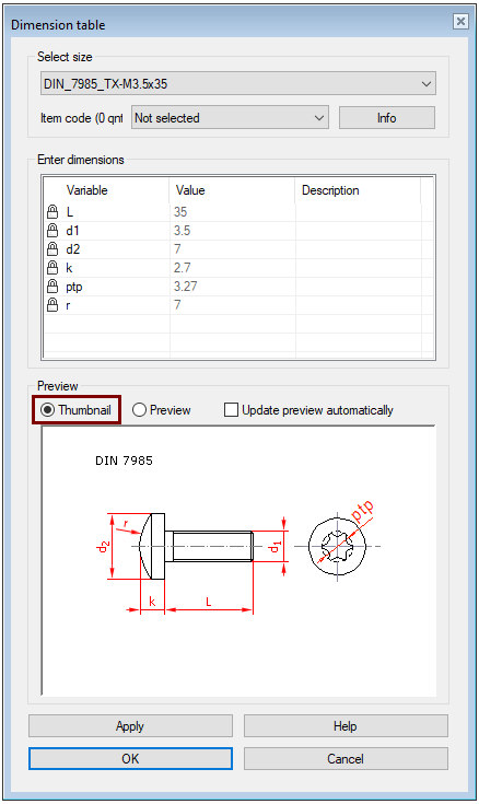
Thumbail is selected
-
From the Thumbnail, you can check the effect of each variable on the dimensions of the component.
-
If there is no dimensioned Thumbnail, then the program displays a preview Thumbnail of the model (which is not updated).
If you want a dimension thumbnail for your own component, do it with an image editing program and save it in png format next to the component with the name of the component with the _2d.png extension, e.g.
-
component.vxm (model file)
-
component.jpg (thumbnail) In older components also .bmp.
-
component_2d.png (Dimensioned Thumbnail)
Preview is selected
-
If the Update preview automatically option is selected, selecting the dimension row row immediately updates the figure of the component to the correct size.
-
With some geometrically heavy components, the automatic preview image update does not keep pace with fast line breaks, so you should remove the above option and use the Apply if necessary.
-
Analyze the assembly model
Sometimes the behavior of a assembly model may be surprising and you need to figure out why it is behaving differently than usual.
Now the model analysis tools have been gathered in one place from which the analyzes can be easily performed.
If you approach Vertex Systems Oy's support service for any problems with your models, we recommend that you always attach the model to your support request first. If for some reason this is not possible, perform a full analysis of the model (with the Select All option) and copy the entire text to the problem report.
Analyze the assembly model with the Analyze toolbar function. This function opens a dialog where you can select the objects to be analyzed. Use the Apply button to perform the analysis and list the findings in a dialog.
-
Note that you can copy text from the dialog using the clipboard.
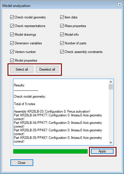
Items to be analyzed
Check model geometry
-
The program analyzes the sketch constraints and reports under- or over-definitions of the sketches.
-
Note that Vertex G4 does not force you to make sketch that are fully defined with constraints. In particular, sketch of dimensionally variable models (such as those used in Product Automation System) should be fully defined.
-
The program also analyzes the flawlessness of the Acis geometry of the configurations in the model.
Check configurations
-
The analysis prints the number of configurations and the names of the configurations in the model.
Model drawings
-
The analysis prints the number of drawings in the model and the names of the drawings.
Version number
-
The analysis tells you which version of the model was originally made.
-
Note: If the model was made with a version older than 15.0.00 (released in September 2008), then the program will not find such information about the model, so it will give a blank answer.
Model properties
-
The analysis indicates whether the part is shown in the assembly parts list or assembly drawing, how the part symmetry is defined (this is important if the part is mirrored in the assembly), whether the part auxiliary geometry (construction lines and planes) is shown in the drawing and and whether the part is permitted to be machined with a machining feature or, if the part is transparent, whether it is shown in the assembly drawing.
-
The Right-click function: Properties opens an dialog where you can change properties.
Item data
-
The analysis tells you the model item ID and description or the item is missing.
Mass properties
-
Analyze part volume, mass and center of gravity location, and moments of inertia with respect to center of gravity.
-
You can get the same information with the Mass function.
-
You can influence the density that significantly affects the mass with the right-click function Item Data, where the material iten or material used is stated.
Number of elements by types
-
The analysis tells the types and numbers of the geometric elements.
-
This information tells to how much of your computer's resources are needed.
-
The information can be useful when wondering about the strange behavior of imported parts; Planar surfaces are spline surfaces, in which case it is not possible to assign distance constraint to them.
-
You can change the planar spline faces of the imported parts to plane faces with the right-click function ACIS Geometry > Healing and then with the Simplification Settings
Check assembly constraints
-
The analysis looks for sub-definitions of the parts and reports as an error if the part has degrees of freedom.
-
Note that the Vertex G4 is not forced to complete a perfectly constrainted assembly. If you do not add a sufficient number of constraints between the parts, then the parts may move out of place, when the assembly solution.