

Exercise 9: Tubelaser
This exercise was carried out with version 27.0 (Vertex 2021).
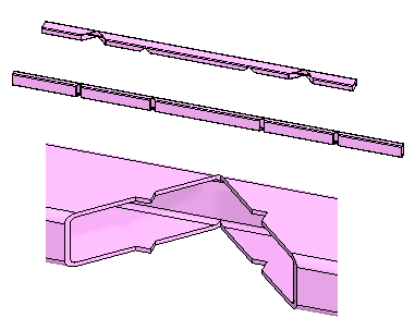
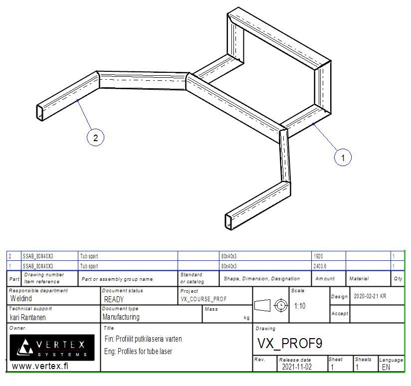
The structure previously described above was always made by first cutting all the profiles and then welding them, often with a jig.
An alternative to this is a tube laser, in which the laser is used to machine cavities in the profiles bends, from which the tubes are folded together and then welded. This method reduces the need for jigs or may eliminate the need altogether.
In this exercise you will learn to
-
We repeat the functions typical of profile structure design.
-
Trim profiles to the library part.
-
The library part ("tool") determines the desired formats for trimming and ensures that it is possible to export multiple profile snippets into one section for a tube laser machine tool.
-
How to create a Step file for a tube laser machine tool.
-
To edit the drawing parts list.
Functions to be used:
-
New local part of the assembly.
-
Sketching: Polyline, two point line.
-
Sketching: Coincident and distance constraints.
-
Add > profile.
-
Trim profiles > Library Part.
-
Other Export > Profiles to stp file.
-
Properties of part > To Assembly Parts List.
-
Properties of part > To Assembly Drawing.
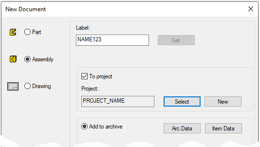
Create a new assembly
-
File > New > Assembly.
-
Enter the label (which is also the name of the model and by default will be the name of the drawing).
-
Enter the archive information by clicking Arc.Data.
-
Select the project where the model will be saved.
-
OK.
-
Create a new local part (Skeleton - Guide curve)
-
Right-click function: New > Part
-
Enter a name, eg SKELETON or JIG.
-
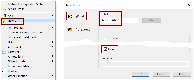
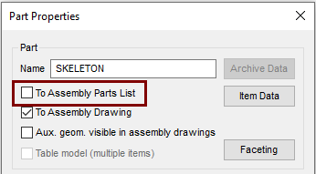
Define that the control curve part does not appear in the parts list
-
Right-click function: Properties
-
Deselect the settings: To Assembly Parts list, because this part is not desired in the parts list, after all it is a completely "intangible" part.
Sketch the first skeleton (guide curve)
-
Right-click function: New Sketch > To vertical (XZ) plane.
-
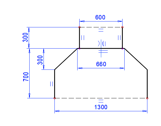
Sketch the lines as shown. (Polyline).
-
Sketch the shape symmetrically with respect to the vertical axis of the origo.
-
Add a coincident constraint between to the horizontal line (660mm) with the horizontal axis of the origo.
-
Operation
-
Guode Curve.
If the guide curve is not visible, then it is because the auxiliary geometry is hidden.
-
Use the

Sketch the second guide curve
-
Restore the Vertical(XZ) plane, if it is not already visible. (From Feature Tree: Restore).
-
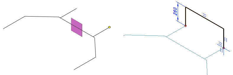
Click the Vertical (XY) plane and end point of line (Remember Ctrl-key). In the figure on the left.
-
Right-click function: New Sketch.
-
Sketch the polyline, height 260. In the figure on the right.
Operation
-
Guode Curve.
Hide the auxiliary plane if it interferes with your work.
If the Perpendicular setting was selected in sketch, the program might turn the model as if it were upside down.
-
Before drawing a sketch, make sure the direction is correct by rotating the model with the Isometric View button on the toolstrip.
-
You can also sketch well in isometric projection.
Exit from part to assembly
-
OK.
Add profiles
-
Right-click function: Add > Profile.
-
Select the profile from the library Profiles > Tub_spar > SSAB_10219_RECTANGULAR.
-
Select size: SSAB_80x40x3.
-
Select the trimming mode: Trim automatically to edge, or Don't trim automatically.
-
Make sure the profile is "upright".
-
If necessary, rotate the profile cross section 90° using the right arrow or left arrow keys or the Rotate left or Rotate right buttons in the auxiliary menu.
-
-
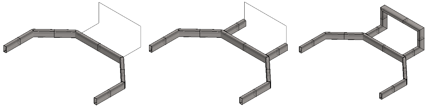
Click the five lines on the bottom. In the figure on the left.
-
Select the trimming mode: Trim automatically to face.
-
Click the two lines on the bottom. In the figure on the center.
-
Select the trimming mode: Trim automatically to edge, or Don't trim automatically.
-
Click to the remaining three lines.
-
If necessary, rotate the profile cross section 90° using the right arrow or left arrow keys or the Rotate left or Rotate right buttons in the auxiliary menu.
-
If your intention is to combine individual profile parts into a single tube needed by a tube laser, then adding profiles does not require edge (miter) trimming between the profiles, but is done later when the profiles are trimmed into the library part.
Trim profiles to the library part
Method 1 (Profiles first):
-
Click two adjacent profiles. (Remember

-
Right-click function: Trim profiles > To Library Part.
-
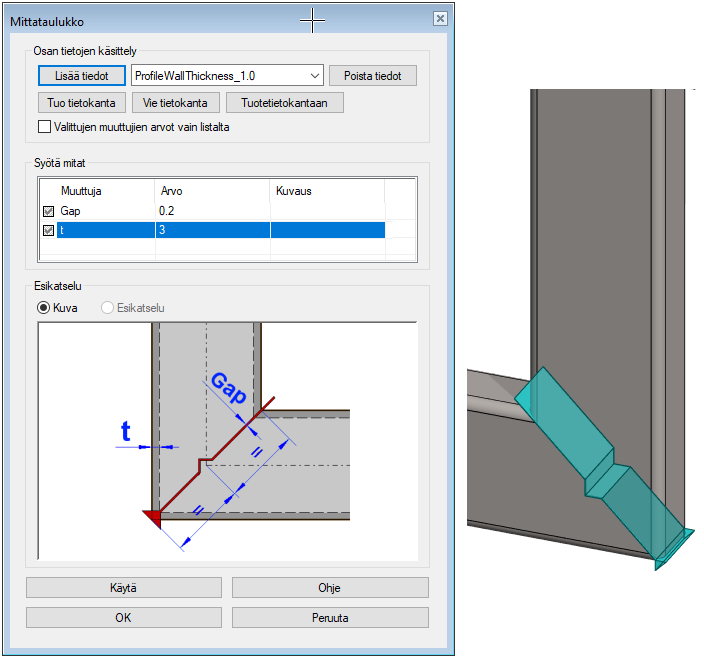
Select: TrimParts > Pipelaser > Pipelaser2.
-
Change the value of the variable t describing the wall thickness to 1 > 3.
-
If necessary, change the value Gap, which is the size of the welding gap.
-
OK.
-
etc.
-
Method 2 (Tool first)
-
Press B to open the universal browser.
-
Choose tool: Libraries > Profile Trim Parts > Pipelaser > Pipelaser2.
-
Click two adjacent profiles. (Ctrl no need).
-
Change the value of the variable t describing the wall thickness to 1 > 3.
-
If necessary, change the value Gap, which is the size of the welding gap.
-
OK.
-
Click next two adjacent profiles.
-
etc.
-
-
Stop trimming profiles with the V, or Esc key or the middle mouse button.
The method is faster if you can use the same tool for all profile trimming.
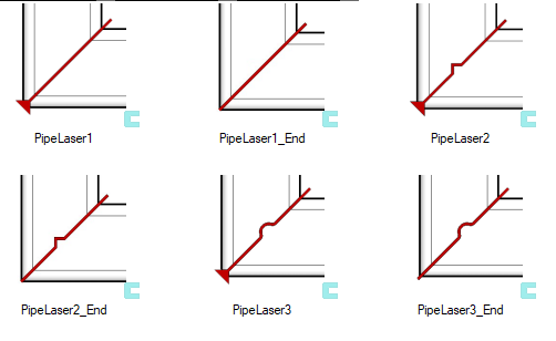
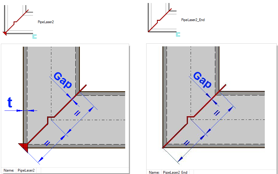
At the point in the closed frames where the pipe begins and ends, the tool ending in _End is to be used.
-
Other tools remove the amount of material from the corner by the thickness of the wall, but the tools with suffix _End do not.
Export the Step file for the tube laser machine tool.
-
Click one of the profiles in the chain of profiles trimmed with the PipeLaser * tools.
-
Right-click function: Other Export > Profiles to stp file.
-
Select the directory where the Step file will be saved.
-
Accept or change the file name.
-
Save
Do this twice, that is, once for both "profile chains".
The program suggests a name for the Step file, the beginning of which is the assembly model ID and the rest is the index number of the selected profile.
You can see the indexes of the parts in the model feature tree:
-
In the feature tree, click the main symbol.
-
Right-click function: Tree > Tree data.
-
Deselect: Default.
-
Select from the list: Index (and partname)
The index tells the order in which the parts were added to the assembly and starts with the number #100.
-
If there are no all numbers in between, the part has been removed from assembly.
View Step files
-
Drag the exported Step files to the Vertex G4 desktop.
-
Accept the dialog defaults.
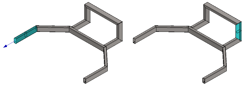
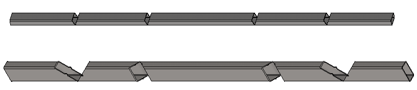
These step files are exported to a tube laser machine tool that cuts the tubes.
-
After machining, the pipes can be bent into their shape and welded to their bent shape.
-
Such fabrication reduces the need for welding jigs.
Create a drawing for the model
For more detailed instructions, see the Modeling parts course exercise 5 Drawing of Model.
Parts listing does not meet the needs of a tube laser.
When you generate a parts list from profiles, each different profile in the model is presented in the parts list separately.
-
However, if the selected sections of the profile structure are made with a tube laser, in which the individual profiles are combined with the function Other Export > Profiles to stp file
into a single tube, then the parts list does not tell the truth about the required profiles. For the needs of the profiles (length and total weight) it instead fits well.
Remove from the list those profile sections that are part of the laser-machined tube:
-
Click on the profile.
-
Right-click function: Properties.
-
Deselect: To Assembly Parts List.
Add to the assembly the step files that you exported and process them.
-
Analyze their length with the function: Distance.
-
Click the (imported) profile part.
-
Right-click function: Item data.
-
Enter the ID and description.
-
Enter the dimensions of the profile cross-section in the Dimensions field. In this exercise 80x40x3.
-
Fill Amount field.
-
Enter the profile length in the Amount field.
-
Click the (imported) profile part.
-
Right-click function: Properties.
-
Deselect: To Assembly Drawing.
If you want the part numbers in the drawing after the previous tricks, please note that the program cannot find parts No. 1 and 2 in the drawing, because they are not in it. However, assign part numbers to the geometry.
Save the model
-
File > Save or click


Download the model (VX_PROF9.vxz) here.