

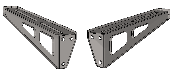
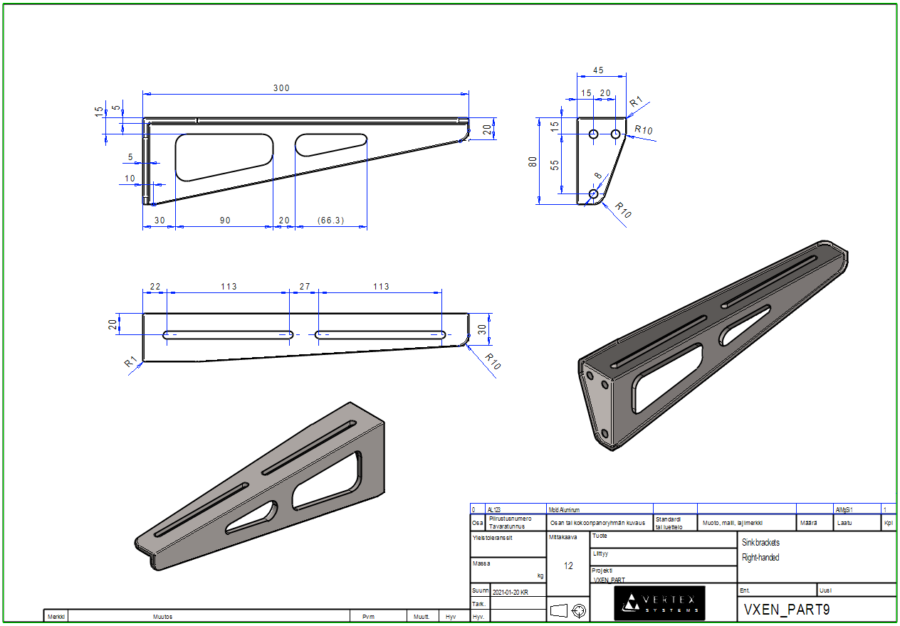
Exercise 9: Sink brackets
This exercise was carried out with version 27.0 (Vertex 2021).
In this exercise you will learn to
-
Add and naming a new configuration of part.
-
Mirror the entire part (e.g. from right-handed to left-handed or from half-model to a symmetrical model).
-
Visually inspect the feature to be added to the part before adding it.
-
Different roundings: In one line, to a point, to a chain of lines
-
How to copy a drawing from one configuration to another configuration.
Functions to be used:
-
Review sketching tools.
-
Operation: Boss Extrusion and Cutout Extrusion. Extrusion: Flip Directions.
-
Library feature > Cutout
-
Mirror
-
Item data, material data
-
Configuration > Add Configuratio, Configuration > Properties > Name
-
Drawing > Copy (as a new drawing for another configuration)
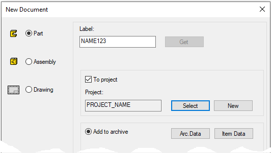
Create a new part
-
File > New > Part.
-
Enter the label (which is also the name of the model and by default will be the name of the drawing).
-
Enter the archive information by clicking Arc.Data.
-
Select the project for the model.
-
OK.
-
Create the first feature
-
New Sketch > To vertical (XZ) plane.
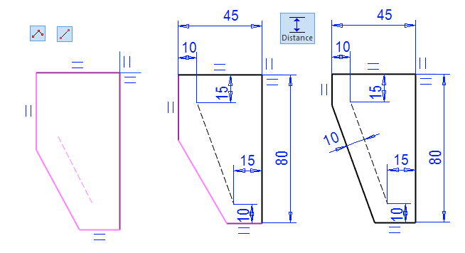
Sketch the shape
-
The function: Polyline and Two Point Line.
-
Line style: Shape, except the guide line style: Guide.
-
-
Start from the origo.
-
With the help of the guide line, you can control the shape so that the rounding added to the part is at a constant distance from the mounting hole.
-
-
Add dimension constraints.
-

Operation
-
Boss > Extrude.
-
Lenght: 5.
Create the main support to the bracket
-
Click side face
-
Right-click function New Sketch > Face
-
or New Sketch > Lateral(YZ) Plane.
Sketch the shape
-
Look at the figure. (Note directional locks.)
-
Operation
-
Boss > Extrude.
-
Lenght: 5.
-
Flip (direction of extrusion).
Create the horizontal support
-
Click top face.
-
Right-click function New Sketch > Face
-
or New Sketch > Horizontal(XY) Plane.
Sketch the shape
-
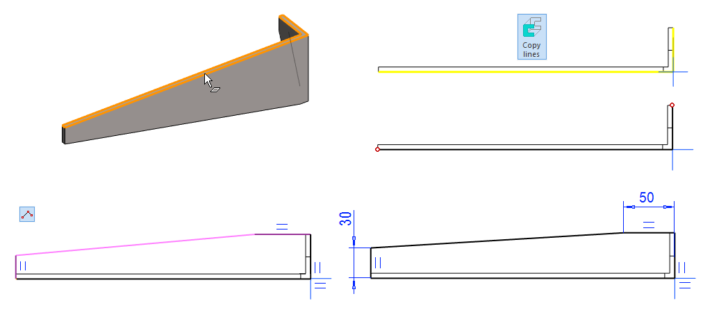
Click the lines from the geometry (shown in yellow) and the right-click function: Copy lines (Copy to Sketch Plane).
-
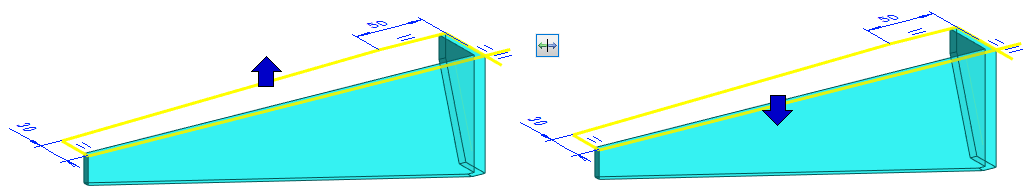
Sketch the remaining lines (Note the direction locks - or add the necessary constraints).
-
Add dimensions (50 and 30).
-
Operation
-
Boss > Extrude.
-
Lenght: 5.
-
Flip (direction of extrusion).
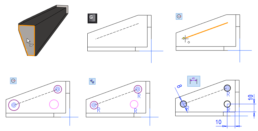
Model the circle mounting holes.
-
Click the front face.
-
Right-click function: New Sketch > Face.
-
If the guide line is not displayed, press G key.
Sketch the shape
-
Sketch three circles.
-
Click the end point of the control curve as the center point for two of them.
-
-
Click three circles (Remember the Ctrl key) and the Right-click function: Constraints > Equal Radius.
-
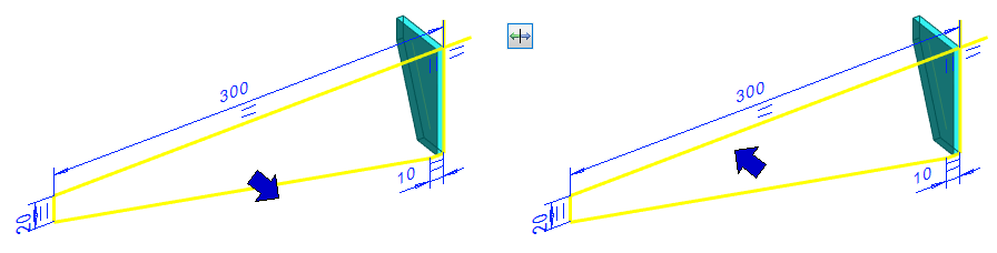
Add dimension constraints
-
Diameter of the circle: 8.
-
Distances of the center of the free circle from the inner edges of the brackets: 10.
-
-
Operation
-
Cutout > Extrude.
-
Thru all
When you start the equal radius constraint first and then click to the first circle, the equal radius symbol appears next to the cursor.
-
1: Select two circles that get the same radius (by default, the first-clicked circle retains its diameter unless the second-clicked circle has constraint that limit its size).
-
2: You can click several circles and they all get the same radius as the first circle.
Model the first longitudinal mounting hole
-
Add the first hole using the library feature.
-
Right-click function: Library Feature > Cutout.
-
Or Function: Cut (Add Cutout using feature from library)

-
-
Select a feature from the library: Feature > Standard > Basic_Shapes > Oval.
-
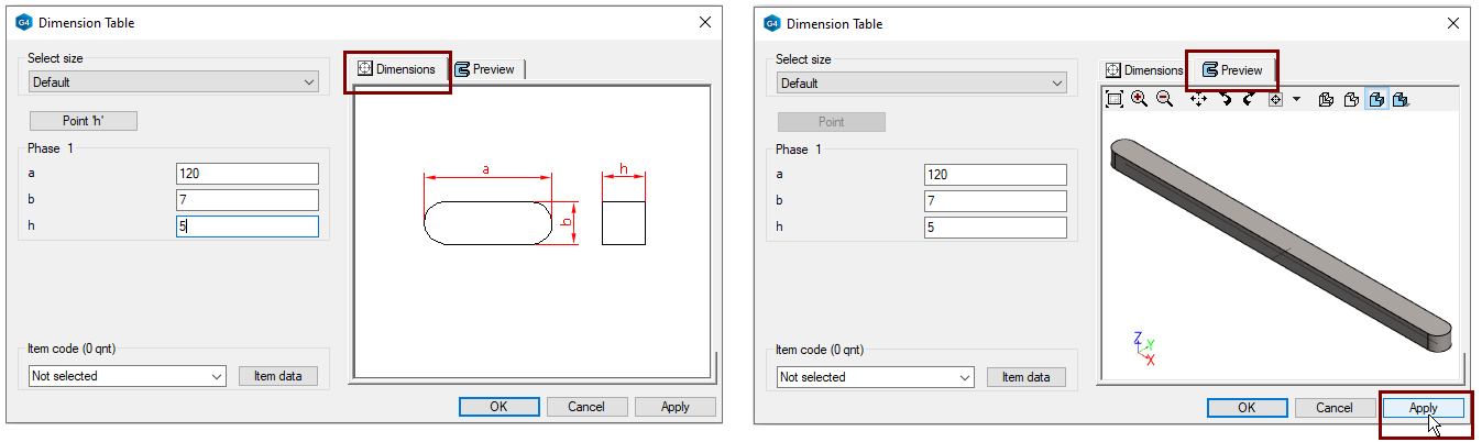
Enter the dimensions of the feature in the Dimension table:
-
a= 120, b= 7 ja h= 5.
-
OK.
-
-
Move the cursor over the top face of the model.
-
If the feature is in the wrong position, use the menu buttons in the upper-left corner of the desktop to rotate it.
-
-
Click to place the feature on the surface.
-
Use a Distance or Dimension constraints to locate the feature
-
22 from end and 20 from side
-
-
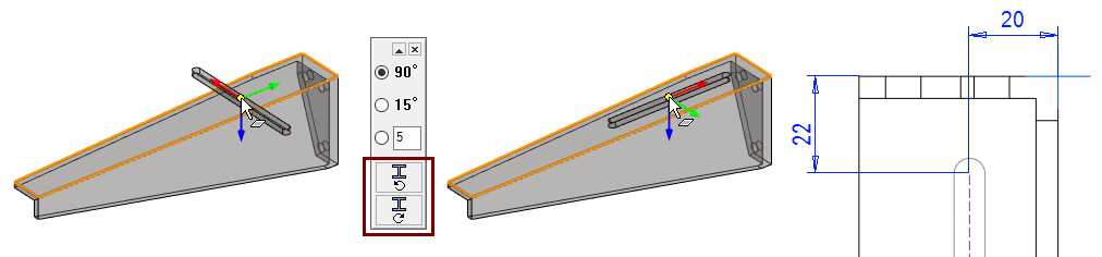
Make a new sketch on the surface and use the function Obround 
-
Click to the first point.
-
Lock the direction.
-
Click to another point or enter the length of the mounting hole.
-
Click to width of the mounting hole or enter the width of the mounting hole.
Next to the fields in the dimension table is a figure of the feature, when the Dimensions tab is selected.
The Preview tab displays the geometry varied to the given dimensions (Use the Apply). In this window, the model can also be zoomed in and viewed from different directions and visualized in different ways.
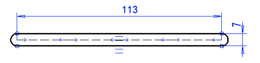
Make another longitudinal mounting hole using a pattern of features
-
Select the mounting hole feature (either from the feature tree or by clicking to one face of the hole).
-
Right-click function: Feature pattern.
-
Pattern Data:
-
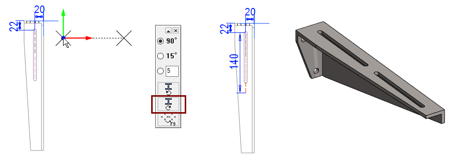
Length-direction, number: 2.
-
Length-direction, delta: 140.
-
-
If necessary, turn the auxiliary geometry parallel to the bracket (90 ° clockwise in the figure).
-
Click the auxiliary geometry to the location (preferably attached to the mounting hole geometry)
-
You could then edit the dimensions of the sketch.
-
-
OK.
Model the relief openings on the side
-
Click the side face.
-
Right-click function: New Sketch > Face.
Sketch the shape
-
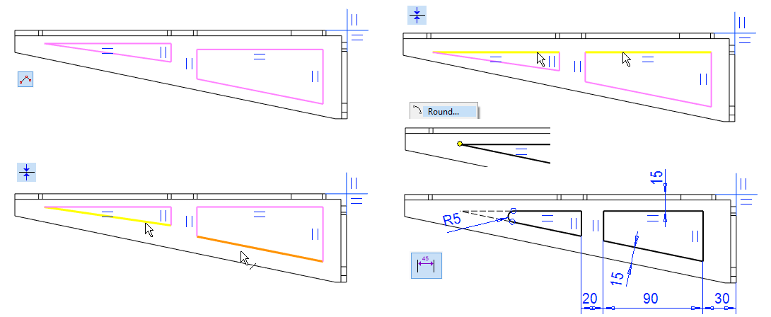
Sketch openings with the function: Polyline.
-
Add a coincident constraint to the top lines (yellow lines) and bottom lines (yellow and orange line).
-
Add a rounding to the sharp corner of the triangle.
-
Click to a point.
-
Right-click function: Round.
-
Enter the value: 5.
-
-
OK.
Operation
-
Cutout > Extrude.
-
Thru all
-
Function: Round

-
Select the lines.
-
Enter the value: 5.
-
Select the other two lines.
-
Enter the value.
-
and so on.
-
-
Press Esc to finish adding roundings.
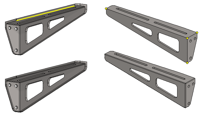
Add individual rounds
-
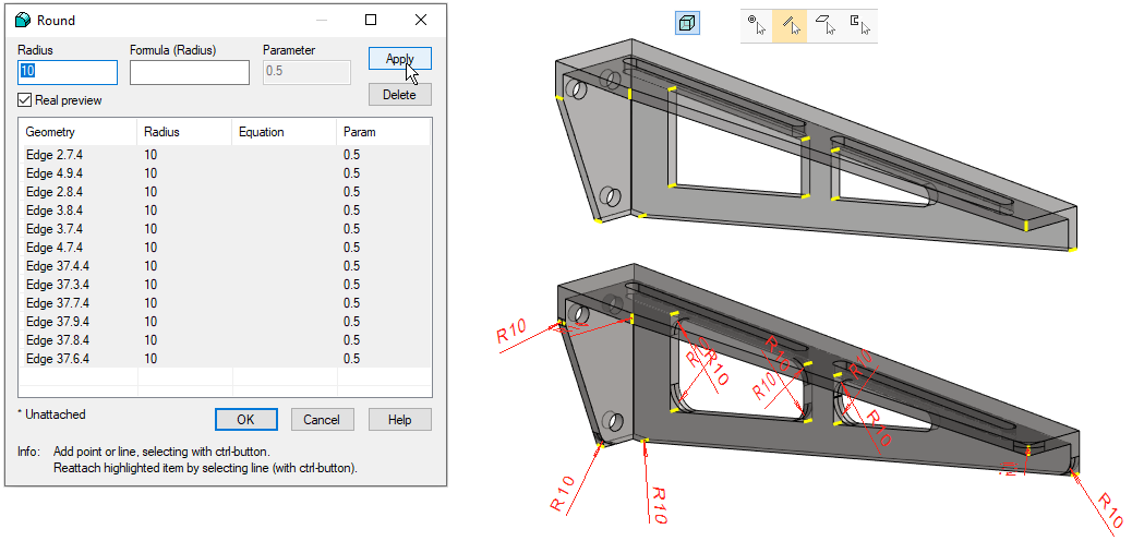
Click lines (12 pcs).
-
Put Transparency on and search Snap to Line, so you can click lines through the faces.
-
-
Right-click function: Add Round/Bevel > Single Edge Round.
-
Enter the radius: 10.
-
To see a preview of the roundings, press the Apply.
-
-
OK.
Add rounding of inner corners.
-
Click the point in the inside corner.
-
Right-click function: Round Point.
-
Enter the radius: 1.5
-
OK.
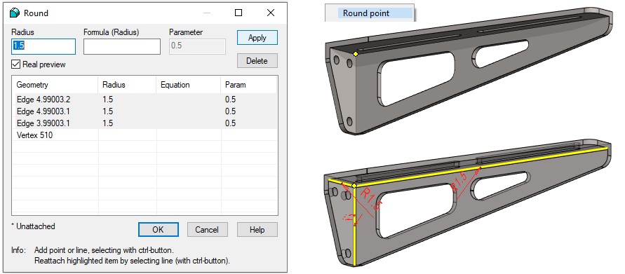
Add rounding according to your needs
-
By selecting a single line, you get to round all the "inside" edges.
-
By selecting four points you can round all the "outer" edges.
If you use a part in assembly where the roundings are barely visible, it would be useful to add configuration in the model where the roundings are hidden.
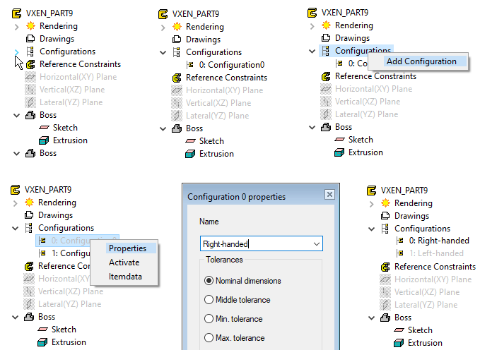
Add a new configuration and enter a name for the configuration
-
In the feature tree, click Configurations to see the configurations in the part.
-
Add a new configuration.
-
Click Configurations.
-
Right-click function: Add Configuration.
-
-
Name the configurations.
-
Click Configuration
-
Right-click function: Properties.
-
Enter the name of the configuration in the menu that opens. For one Left-handed and for the other Right-handed.
-
OK.
-
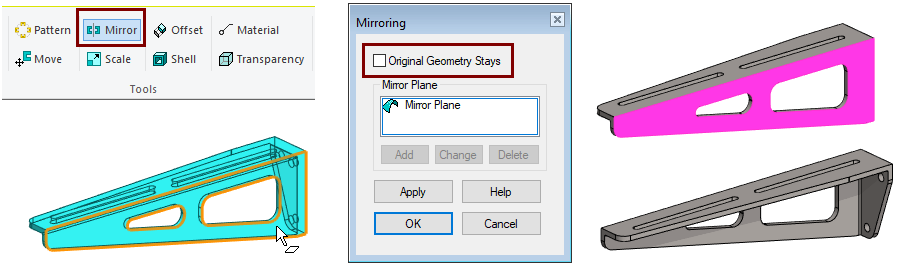
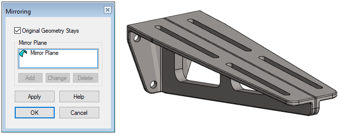
Mirror the model
First double-click the Left-handed configuration (if it is passive = gray) to mirror only this configuration.
-
The function (in the Ribbbon): Mirror (Mirror the whole geometry of the part).
-
Click to the face that acts as the mirror plane.
-
Deselect the dialog: Original Geometrt Stays.
-
OK.
Try the two configurations of the part.
-
Double-click the expression: Right-handed and then the Left-handed configuration.
-
When such a part is later added to the assembly, the program will ask you to select an configuration.
Another way to start mirroring:
-
Right-click function: Edit model > Mirror the whole geometry of part.
Mirroring of a single feature:
-
Select a feature from either the feature tree or one face from geometry.
-
Right-click function: Mirror feature.
-
This function can be used with symmetrical part when you want to copy a feature (Boss or Cutout) by mirroring it on the other side of the part.
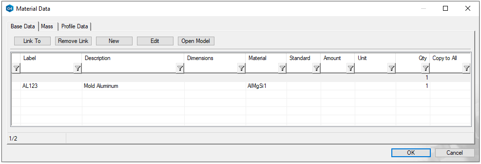
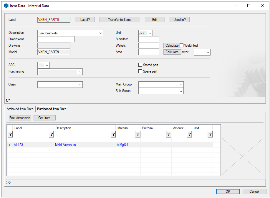
Give the raw material to the part
-
First activate the configuration: 0: Right-handed.
-
Right-click function: Item data (When nothing is selected)
-
For more details, see Exercise 5. Model Drawing. Paragraph: Adding Bill of Material (raw material) for a part.
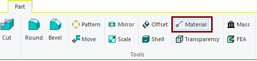
Ribbon Function (Tools) Material opens the Material dialog, where you can write manually or retrieve material information for the raw material.
Create a drawing for a right-handed bracket.
-
First activate the configuration: 0: Right-handed. (If it is passive).
-
Create a drawing and dimension it
-
For more details, see Exercise 5. Model Drawing
-
-
Save the drawing.
-
Remove it from the desktop.
-
Save the model.
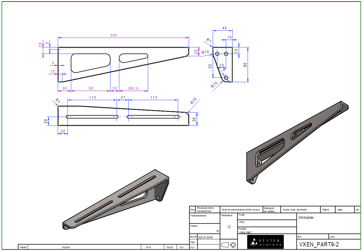
Create a drawing for a left-handed bracket.
-
Open the Drawings and Configuration branches from the feature tree.
-
Activate the second configuration 1 (1: Left-handed).
-
Select the first drawing (shown in passive gray).
-
Right-click function: Copy.
-
Enter archive data.
The program copies the first drawing to a new drawing and at the same time changes all projections of the drawing to describe the geometry according to the active configuration, in this case left-handed geometry.
-
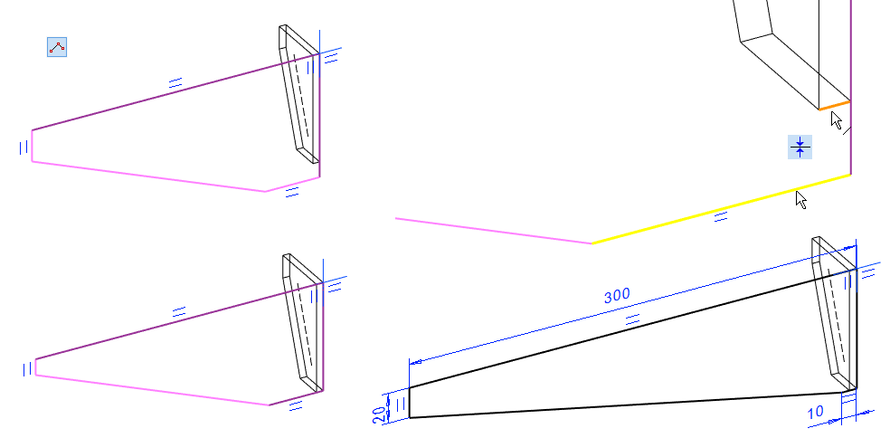
Now some of the dimensions may lose their reference, meaning they no longer know at which line or at what point they are stuck.
-
Dimensions that have lost their Reference appear in purple and will not update if the geometry of the model changes.
-
Purple dimensions should be removed and re-added
It is advisable to modify the copied drawing, for example, by removing projections that poorly describe the model and adding projections taken from better directions.
Save the drawing.
The items and their raw materials are configuration-specific, different configurations can describe not only parts with different geometries, but also parts with different raw materials.
-
As no item data was given for configuration 1 in this exercise, the drawing for this configuration does not show parts list information either.
Save the model
-
File > Save or click


