

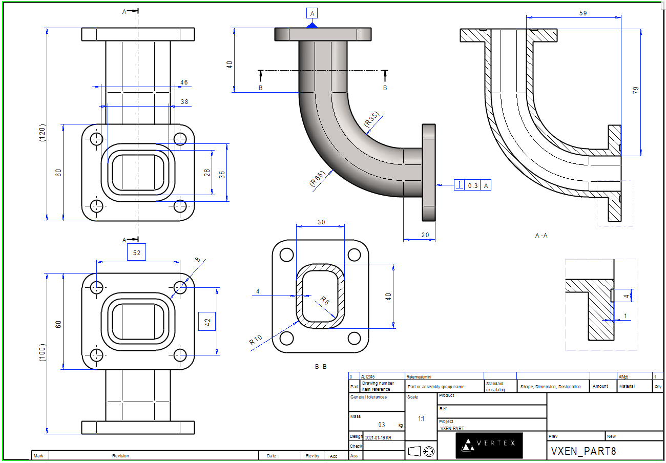
Exercise 8: Pipe Fittings
This exercise was carried out with version 27.0 (Vertex 2021).
In this exercise you will learn to
-
Create a part using a guide curve and cross section.
-
Saving a sketch to the library and reading it from the library.
-
Copy line of the previous geometry to the sketch.
-
Using the library feature as a cutout feature
-
Create the drawing so that the direction of the front projection is selected.
Functions to be used:
-
We review sketching tools.
-
Sketching: save to Library and Open sketch.
-
Sketching: Copy to Sketch Plane.
-
Operation: Guode curve and Cross Section.
-
Sweep > Boss.
-
Item Data.
-
Drawing > New Drawing.
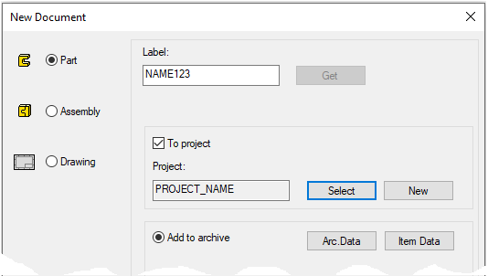
Create a new part
-
File > New > Part.
-
Enter the label (which is also the name of the model and by default will be the name of the drawing).
-
Enter the archive information by clicking Arc.Data.
-
Select the project for the model.
-
OK.
-
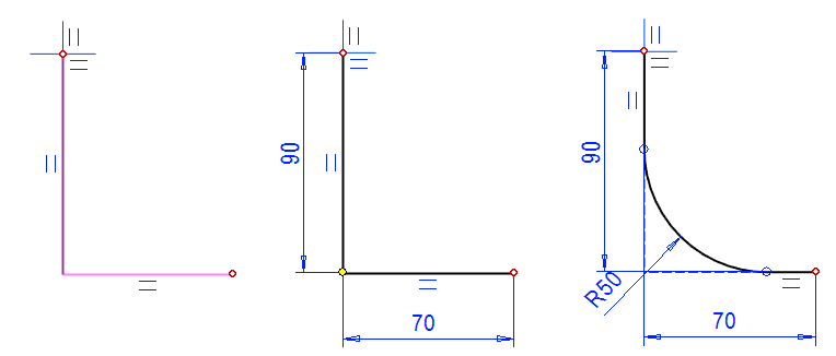
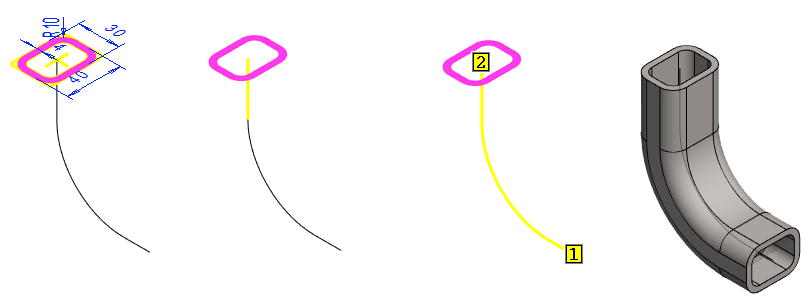
Create a Guide Curve
-
New Sketch > To vertical (XZ) plane
Sketch the shape
-
Sketch lines, polyline. (Start from the origo and direction the line down).
-
Add dimensions. (90 and 70).
-
Click a corner point.
-
Right-click function: Round. (50).
-

Operation
-
Guide Curve.
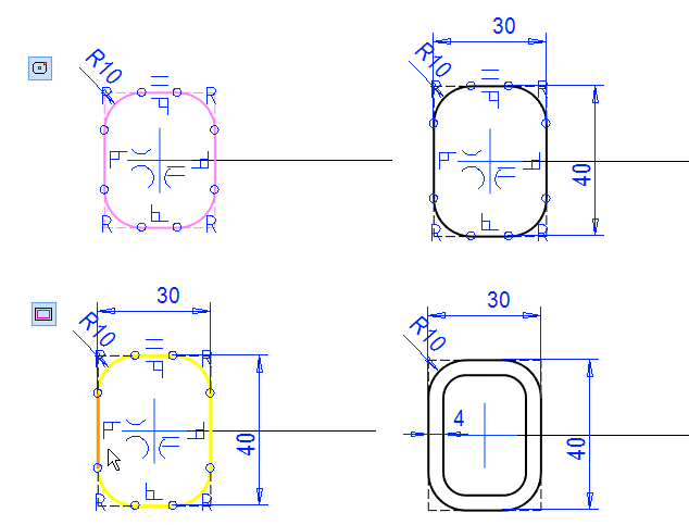
Create Cross Section
-
New Sketch > To horizontal (XY) plane.
Sketch the shape
-
The function: Rounded rectangle of radius 10.
-
Start from the origo.
-
-
Add dimensions to the rectangle: 40 and 30.
-
Use the Offset function to add a parallel copy to the line.
-
Note the option: Line chain to same side.
-
Note the option: Choose line chain.
-
Note the option: Automatic preview.
-
Enter Distance: 4.
-
Click the (Shape) line.
-
Select the side (inside the rectangle)
-
OK.
-
-
Operation
-
Cross Section.
-
The program first asks for the corner radius.
-
Next, the program asks you to click to the center of the rectangle. ("Add rectangle. Select point 1")
-
Finally, the program asks you to click the corner point of the rectangle. ("Add rectangle. Select point 2")
-
A rounding is drawn only if it fits in a rectangle.
-
If the shorter dimension of the rectangle is less than the 2 * radius dimension, the program draws an acute-angled rectangle.
-
Create the pipe using a cross section and a guide curve.
-
Click the Cross Section.
-
Click the Guide Curve.
-
Right-click function: Sweep > Boss.
-
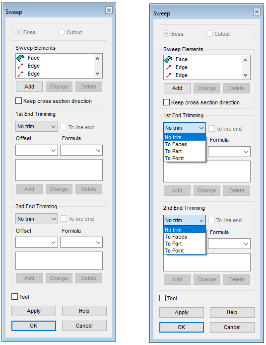
The program finds and selects a tangential line, and opens the dialog Sweep.
-
Accept the defaults.
-
-
OK.
At the top of the dialog you can choose whether the sweep will Boss or Cutout the geometry.
Sweep Elements:
-
The program itself searches for all lines tangential to the selected line.
-
You can also use the Add button to select lines in the chain that are not tangential.
-
Use the Change button to change the selected line to another line (rare).
-
Use the Delete button to delete the selected lines (at the end of the line chain).
Keep cross section direction
-
Normally, the cross-section is always kept perpendicular to the sweep line.
-
With this selection, the cross section slides along the curve in the original position.
1st and 2nd End Trimming.
-
By default, the ends are not trimmed, but the end can be trimmed when the part is modeled in an assembly, on a clicked faces, on another part, or at a point found in the model.
-
With the offset value, the sweep can be extended beyond the line chain (negative value) or left shorter than the line chain extends (positive value).
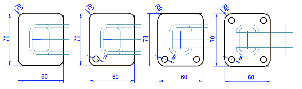
Create the first flange
-
New Sketch > To horizontal (XY) plane.
Sketch the shape
-
A Rounded rectangle of radius 9.
-
Start from the origo.
-
-
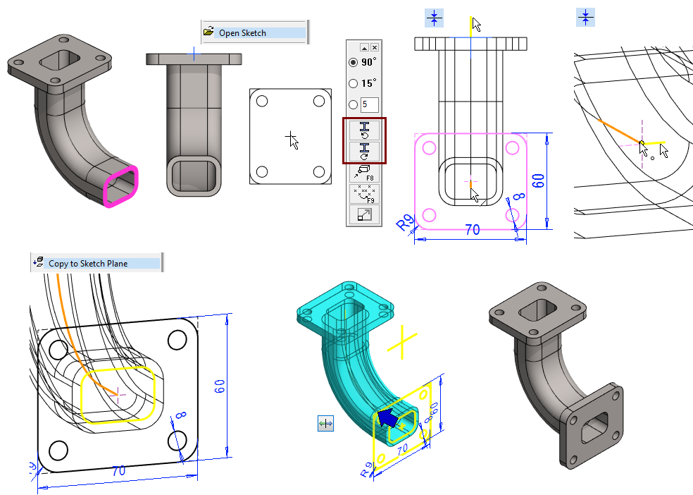
Add dimensions to the rectangle: 70 and 60.
-
Sketch one circle of the same center with the corner rounding, diameter: 8.
-
Mirror the circle around the vertical axis.
-
Mirror the circles around the horizontal axis.
Save the sketch: (Because it is used at the other end).
-
Right-click function: Save to Library.
-
Select a folder or create a new folder.
-
Enter the draft a name, e.g. flange1.
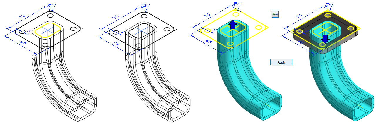
Complete the sketch: (with lines copied from the previous geometry)
-
Copy the lines on the inside edge of the pipe to the sketch, so that the flange does not become sealed.
-
Select lines (Remember the Crtl key).
-
The choice of lines is more illustrative if you turn the model a little so that it is no longer perpendicular View.
-
Right-click function: Copy to Sketch Plane.
-
-
Operation
-
Boss > Extrude.
-
Lenght: 8.
-
Invert the direction

Save the sketch before the operation
Lines copied from the previous geometry of the part get an identical constraint to the previous geometry.
-
The identical constraint can be removed.
-
The identical constraint cannot be added interactively. Instead, a coincident constraint or constraints must be used for this need.
-
It is not advisable to store a sketch with identical constraint in the sketch library, as the lines with such a constraint will later try to find a "partner" in the new model, and when they fail, the draft may "break down."
-
If you trim a line that has identical constraint, then the original line is converted to a contruction line and a trimmed line is generated in its place.
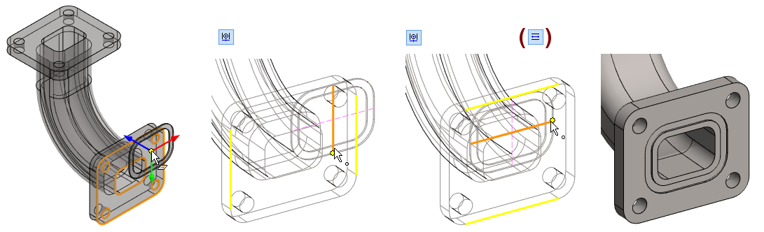
Create the second flange
-
Select the face.
-
Right-click function: New Sketch > Face.
Sketch the shape
-
Right-click function: Open Sketch.
-
Refress Browser (if the sketch you saved is not displayed).
-
-
Place the sketch
-
Turn the sketch if necessary.
-
Place it with coincident constrain.
-
-
Copy the lines on the inside edge of the pipe to the sketch, so that the flange does not become sealed.
-
Select lines (Remember the Crtl key).
-
Right-click function: Copy to Sketch Plane.
-
-
Operation
-
Boss > Extrude.
-
Lenght: 8.
-
Invert the direction
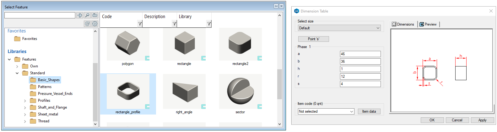
Create a groove for the seals on flange (bottom)
-
Right-click function: Library feature > Cutout.
-
Double click a feature: Features > Standard > Basic_Shapes > rectange_profile.
-
Enter value of Dimension Table dialog:
-
a = 46
-
b = 36
-
h = 1
-
r = 12
-
s = 4
-
-
Place the cursor on the face of the part and make sure that the position of the feature is on the correct face.
-
Place the feature, for example, with the Centering constraint.
-
You may also need to use the Parallel constrain.
-
-
OK completes the feature addition.
Press G to show and hide auxiliary geometry (feature has guide lines)
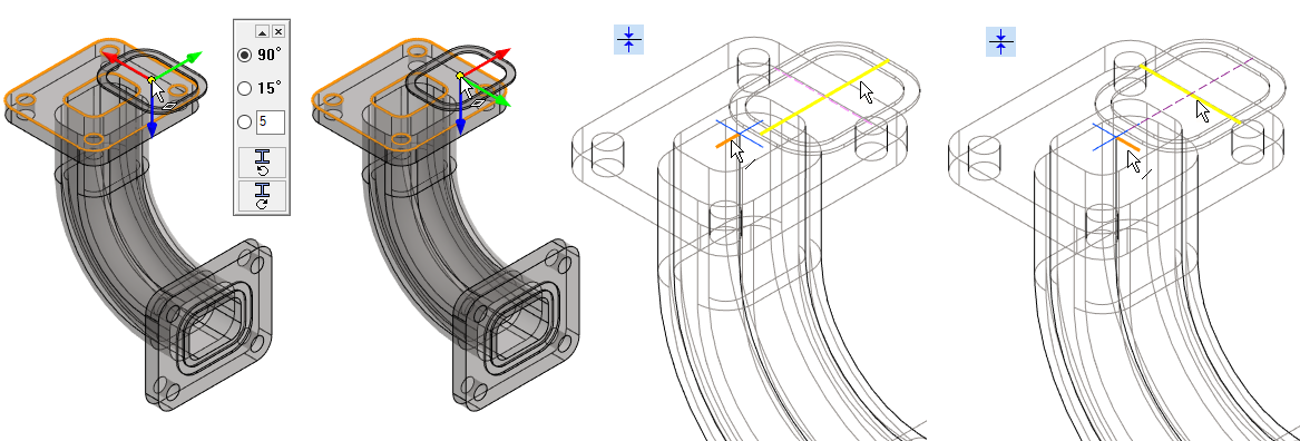
Create a groove for the seals on flange (top)
-
Right-click function: Library feature > Cutout.
-
Double click a feature: Features > Standard > Basic_Shapes > rectange_profile.
-
Enter value of Dimension Table dialog:
-
a = 46
-
b = 36
-
h = 1
-
r = 12
-
s = 4
-
-
Place the cursor on the face of the part and make sure that the position of the feature is on the correct face.
-
Place the feature, for example, with the Coincident constraint.
-
OK completes the feature addition.
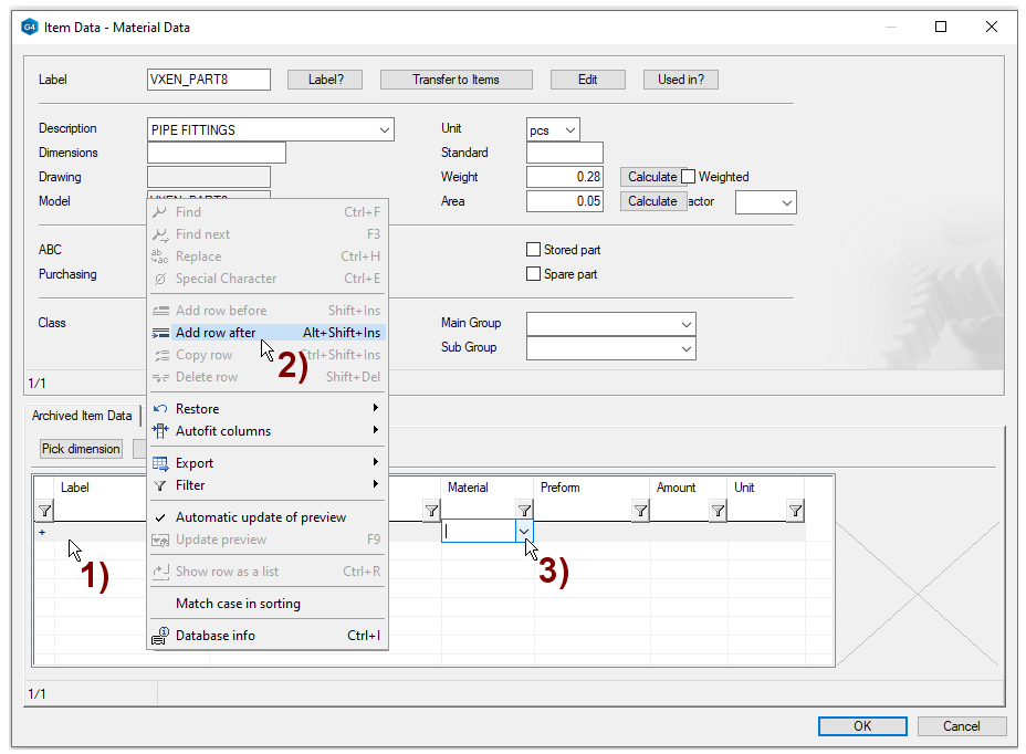
Give item data to the part
-
Right-click function: Item Data.
-
Click on the line in the lower dialog, in the figure 1).
-
Right-click function: Add row after, in the figure 2).
-
Click the preselection button in the Material field, in the figure 3).
-
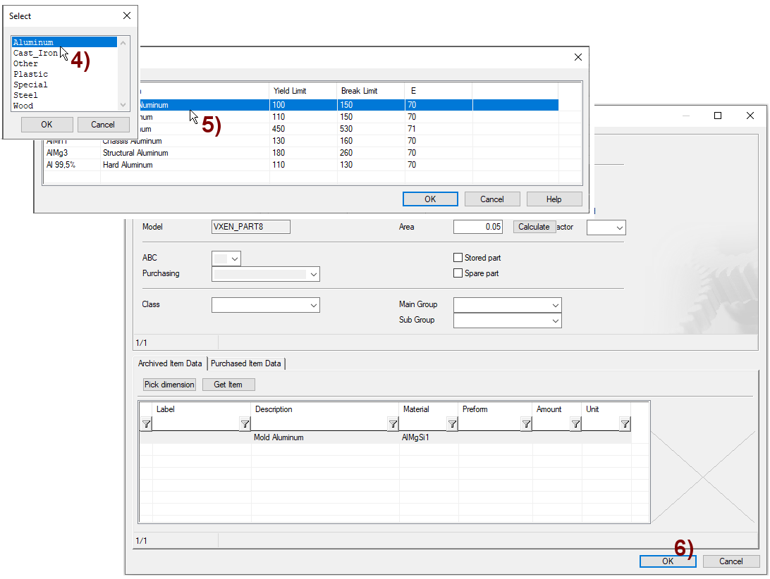
Select: Aluminium (by Double click).
-
Select: AlMgSi1 (by Double click).
-
Also fill in part information (upper dialog), eg weight.
-
Press: Calculate.
-
-
OK.
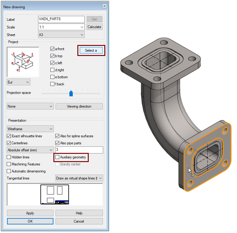
Create a drawing for the part
-
See more detailed instructions for the exercise: 5. Drawing of the model.
-
Drawing > New Drawing (In the feature tree).
-
-
In the dialog New drawing, select data:
-
Scale: 1:1
-
Sheet: A3
-
Select projections: front, top and left.
-
Tangential lines: Draw as virtual shape lines (thin).
-
Remove selection: Auxiliary geometry.
-
-
OK: progress to the archive data.
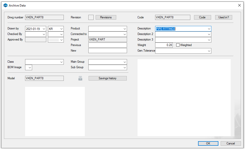
Review and accept the archive information
-
The program copies the archive data to the drawing title bar.
-
Edit the archive data to fit the drawing.
-
OK: accept archive data and create the drawing.
See Exercise 5 for more details
See Exercise 5 for more details
Save the drawing
-
File > Save or click


Save the model
-
File > Save or click