

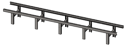
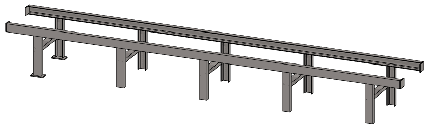
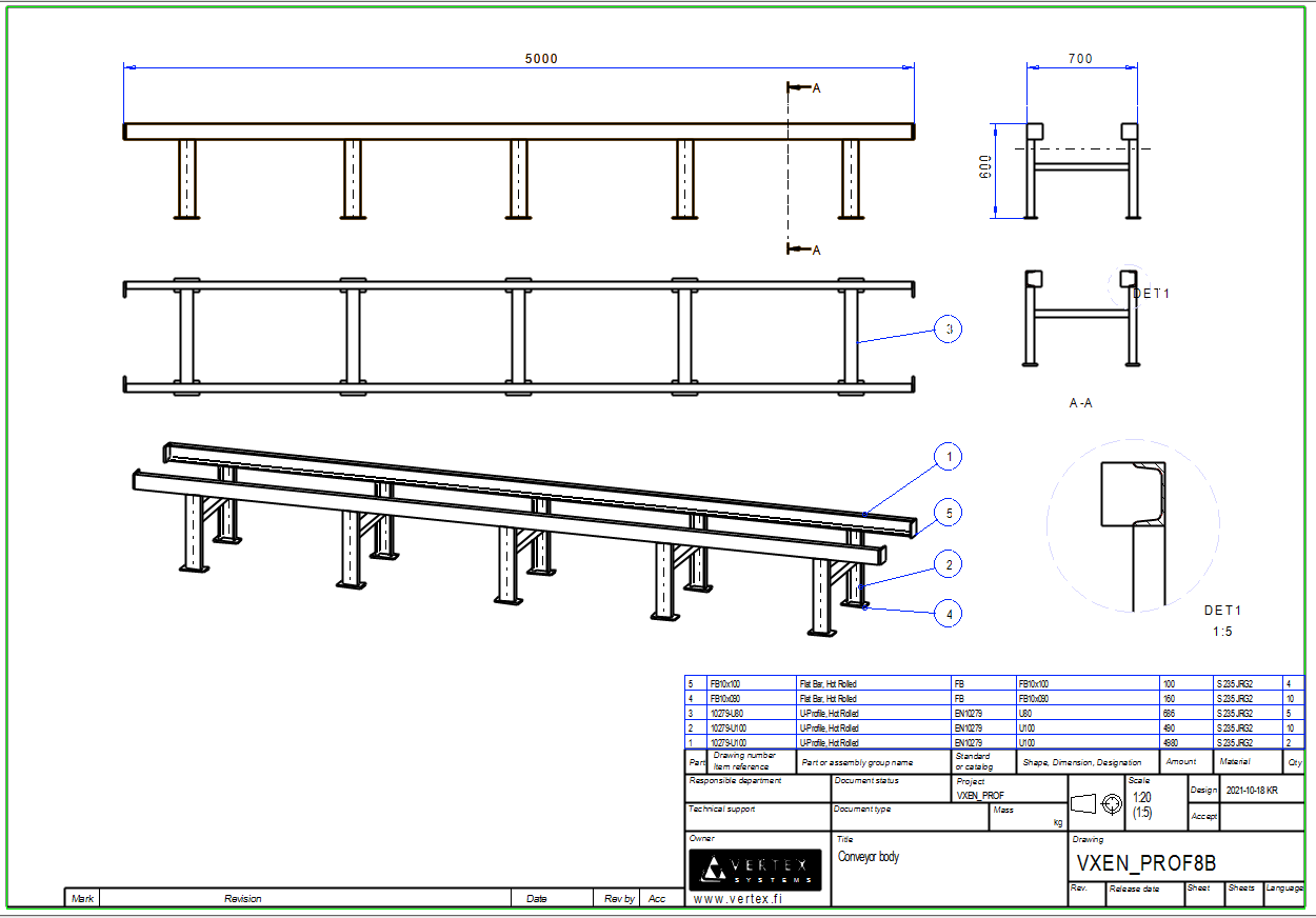
Exercise 8: Conveyor body
This exercise was carried out with version 28.0 (Vertex 2022).
In this exercise you will learn to
-
Use of dimensionally variable guide geometry (SKELETON) to vary the profile structure.
-
In the trimming part of the profile so that there is a welding gap between the parts.
-
To create a pattern of several parts at once.
-
Use the dimension table to vary the profile assembly.
-
To save the model as a new model.
-
To create a part of a pattern based on a previous pattern.
Functions to be used:
-
New local part of the assembly.
-
Sketching: Two point line, rectange.
-
Sketching: Coincident, symmetry and distance constraints.
-
New sketch > Parallel.
-
Add > profile.
-
Trim profiles > To Face.
-
Trim profiles > To Parts.
-
Pattern.
-
Solve.
-
File > save as New.
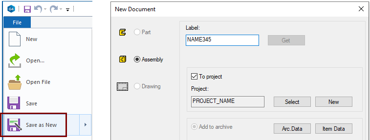
Create a new assembly
-
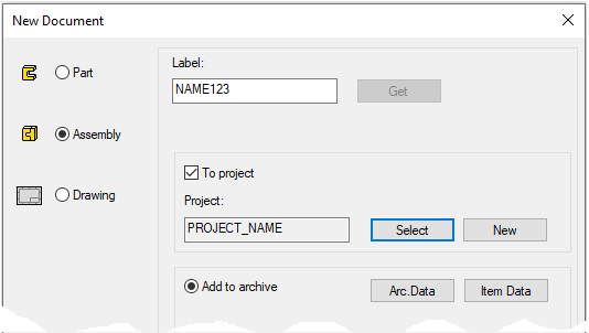
File > New > Assembly.
-
Enter the label (which is also the name of the model and by default will be the name of the drawing).
-
Enter the archive information by clicking Arc.Data.
-
Select the project where the model will be saved.
-
OK.
-
Create a new local part (Skeleton - Guide curve)
-
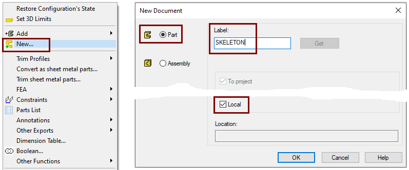
Right-click function: New > Part
-
Enter a name, eg SKELETON or JIG.
-
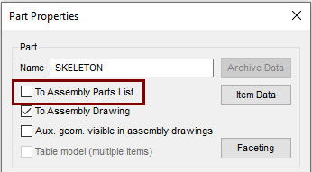
Define that the control curve part does not appear in the parts list
-
Right-click function: Properties
-
Deselect the settings: To Assembly Parts list, because this part is not desired in the parts list, after all it is a completely "intangible" part.
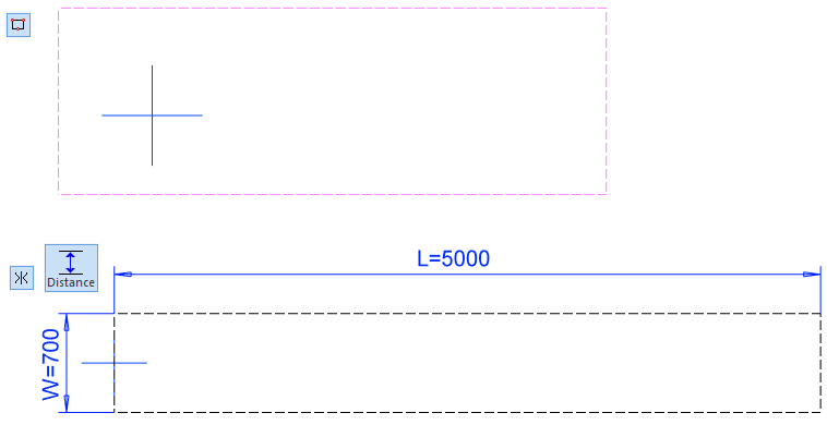
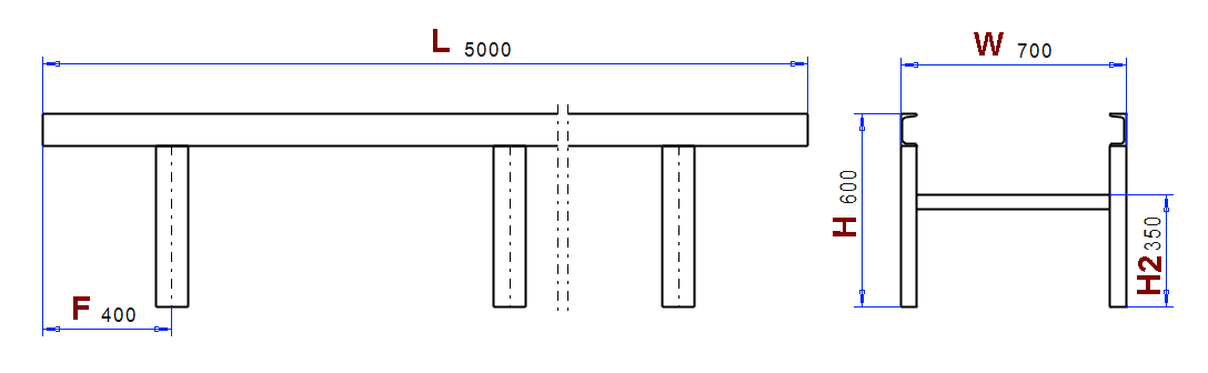
Sketch the main dimensions of the conveyor projected on the floor
It is desired to do the modeling so that the default placement point of the conveyor is at the other end of the conveyor at floor level. In addition, it is desired that the floor have guide lines describing the extreme dimensions (length and width) of the conveyor, which can be used to position the conveyor if necessary.
-
Right-click function: New Sketch > To horizontal (XY) plane.
-
Sketch a rectange.
-
Line style: Guide.
-
-
Add a symmetry constraint between the horizontal lines and the horizontal line of cetral cross.
-
Add a coincident constraint to the left vertical line and vertical line of cetral cross.
-
Add dimensions and formulas.
-
5000 and L.
-
700 and W.
-
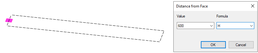
Create a guide geometry that includes the geometry that guides the position of the set of legs
-
Restore the Horizontal(XY) plane, if it is not already visible. (From Feature Tree: Restore).
-
Click the Horizontal (XY) plane.
-
Right-click function: New Sketch > Parallel.
-
Enter the value and formula.
-
600 and H.
-
-
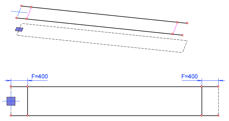
Right-click function: Line > Copy to Sketch Plane.
-
Copy long lines to the sketch plane.
-
-
Sketch two vertical lines and try dragging them to see that their endpoints are attached to the previous lines.
-
If not, add coincident constraints between endpoints and lines.
-
-
Add the distance constraints and formula between the vertical lines and the end:
-
400 and F.
-
Operation
-
Guode Curve.
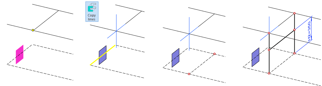
Create a guide geometry for the legs and support
You can hide (or not hide) the horizontal(XY) plane.
-
Restore the Lateral(YZ) plane, if it is not already visible. (From Feature Tree: Restore).
-
Click the Lateral(YX) plane and the point (remember Ctrl key). In the left figure.
-
Right-click function: New Sketch.
-
If you have the Perpendicular setting, the program may turn the conveyor upside down.
-
Rotate the model, e.g., in the isometric direction.
-
-
Function Copy lines or right-click function: Line > Copy to Sketch Plane
-
Copy the end line (yellow line in the figure) to the sketch plane.
-
-
Change the line to a construction line, because it is only needed in this sketch.
-
Sketch two vertical lines whose endpoints coincide with the endpoints of the diagonal lines.
-
Sketch a horizontal line between the lines.
-
Add a distance constraint with formula between the horizontal lines.
-
350 and H2.
-
Operation
-
Guode Curve.
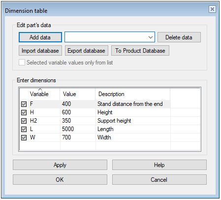
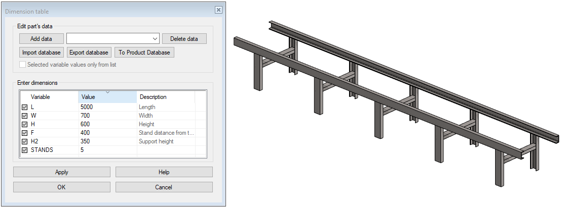
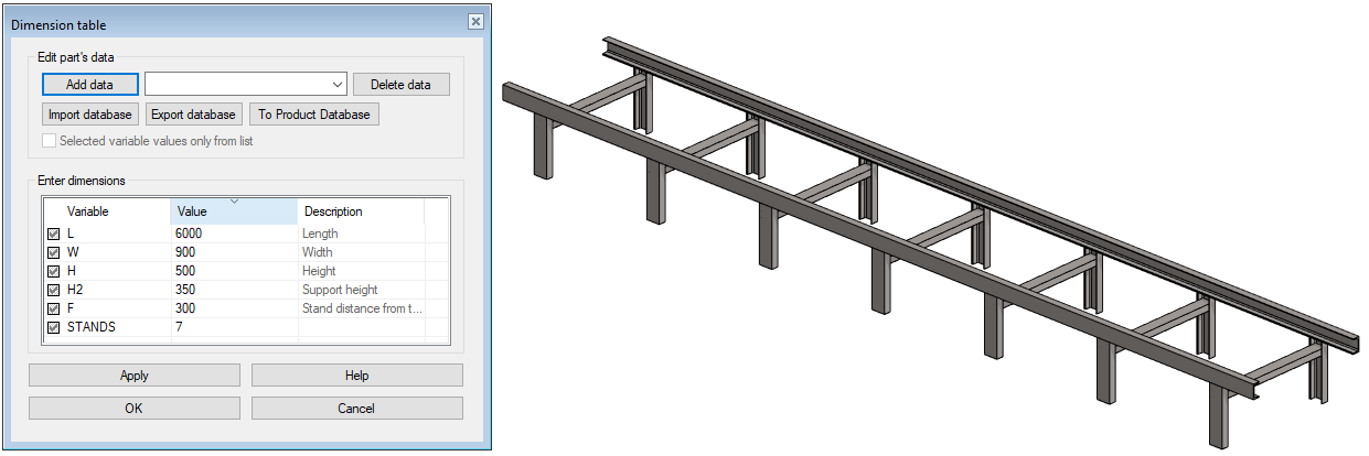
Enter a description for the variables
-
Right-click function: Dimension Table.
-
Enter descriptions.
Click a heading to sort the rows by ascending or descending order by heading.
-
OK to save the changes.
Exit from part to assembly
-
OK.
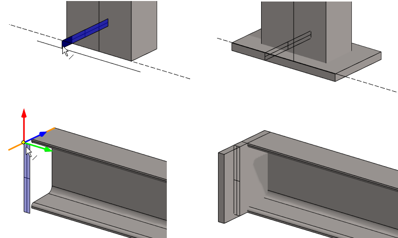
Add the main supports
The main dimensions of the conveyor body were given in the sketch. The profiles must be positioned so that the main dimensions do not increase, so the default placement point (center point) is not valid. In addition, it is desired that the U-shape open in the direction of the center of the conveyor.
-
Right-click function: Add > Profile.
-
Select the profile from the library Profiles > Hotrolled > EN_10279-U30-300.
-
Select size: EN_10279-U100.
-
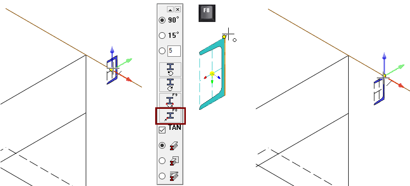
-
Hover over the line (left image) and press F8 (


-
Click to the corner point of the cross section. (middle figure).
-
Click the guide line to add a profile.
-
If necessary, then rotate the profile as needed with the right arrow or left arrow keys.
-
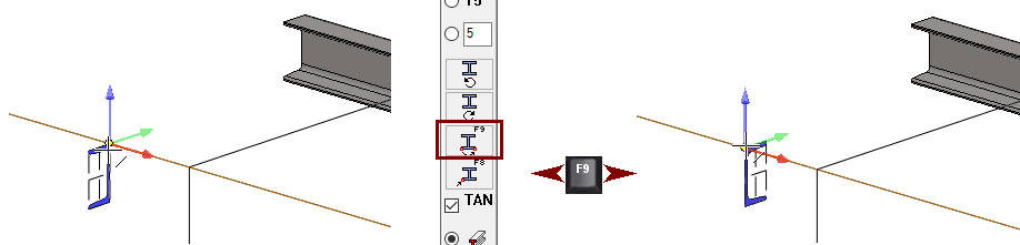
-
Hover over the line (left image)
-
If the cross section opens in the wrong direction, mirror it with F9. (


-
-
Click the guide line to add a profile.
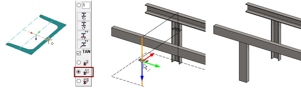
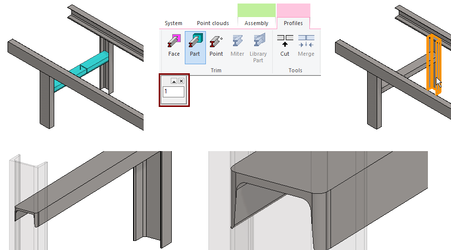
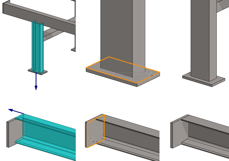
Add legs. Use the same profile
-
Change the attachment point of the profile to the center of the outer edge.
-
Switch to trimming mode on the: Trim automatically to face.

-
Add the profiles so that they open towards the center of the conveyor.
-
If necessary, then rotate the profile as needed with the right arrow or left arrow keys.
-
-
Click the guide lines to add a profile.
-
Press

If you stopped adding profiles before adding legs, you can easily add a similar profile.
-
Click on the profile.
-
Right-click function: Add > Same profile.
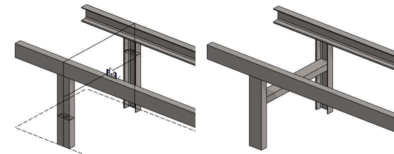
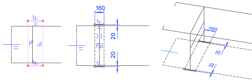
Add a transverse support between the legs
-
Right-click function: Add > Profile.
-
Select the profile from the library Profiles > Hotrolled > EN_10279-U30-300.
-
Select size: EN_10279-U80.
-
-
Change the attachment point of the profile to the center of the outer edge.
-
Rotate the profile so that it opens downwards.
-
Click the guide line to add a profile.
-
Press
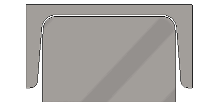
Trim the transverse profile to the legs
-
Click on the profile.
-
Function: Trim profiles to parts.
-
Enter Gap: 1.
-
Click the target profile.
-
OK performs trimming.
-
Trim both ends separately.
Crate a pattern of stand parts
-
Show the auxiliary geometry if it is hidden (G key

-
Hide an other main support to take advantage of auxiliary geometry to define the pattern.
-
Click it and use Hkey

-
-
Select all three stand profiles.
-
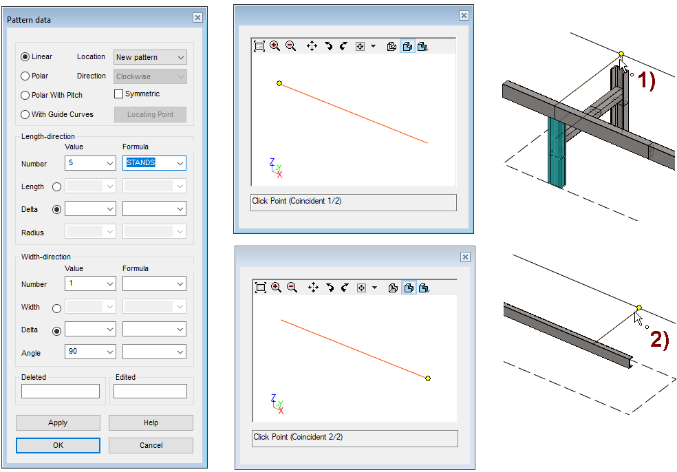
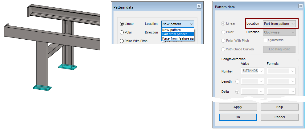
Right-click function: Pattern.
-
Enter the number: 5 and the Formula: STANDS.
-
Do not enter the Length or Delta value, in which case the program will ask for a poits for the model.
-
OK.
-
An auxiliary window appears on the desktop with a line and a dot and the program asks: Click Point (Coincident 1/2).
-
-
Click to the point from guide geometry, In the figure 1).
-
Click to the second point from guide geometry, In the figure 2).
-
The program adds a pattern.
-
Unhide hidden part
-
Right-click function: Restore Hidden.
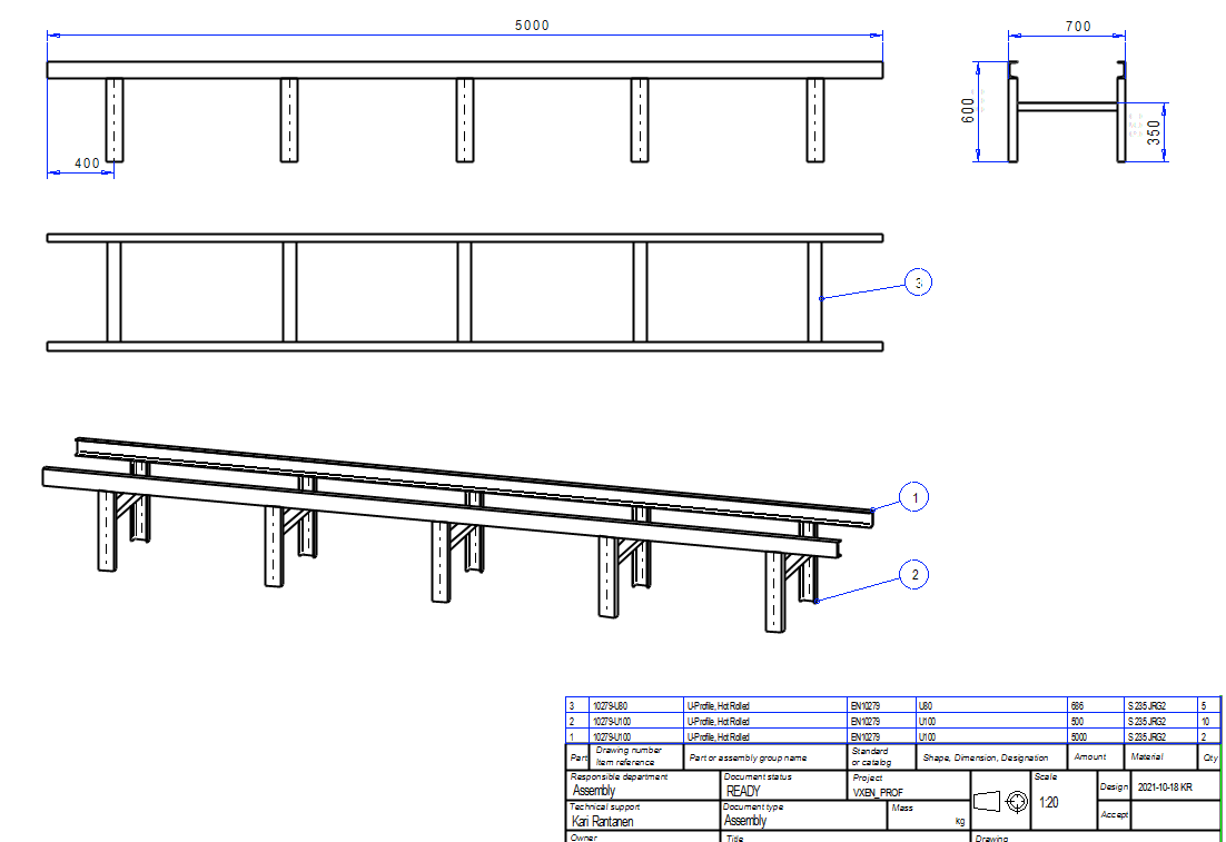
Create a drawing for the assembly
-
Look at detailed instructions: the Modeling parts course exercise 5 Drawing of Model.
-
Save the drawing.
-
File > Save or click


-
-
Remove it form Vertex desktop.
Save the model
-
File > Save or click
Edit the conveyor using the dimension table
-
Right-click function: Dimension Table.
-
Enter the new values.
Because the profiles were placed at their corners, not their centers, the dimensions of the conveyor will be exactly the dimensions you enter in the dimension table.
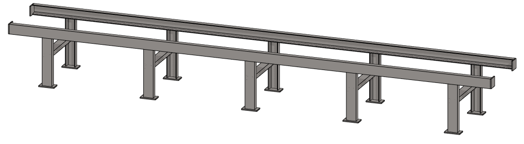
Conveyor with plate of feet and end plates
Create another version of the conveyor with plate of feet and end plate.
Save the model as a new model
-
File > Save as New.
-
Enter a name (ID) and edit the archive information.
Complete the sketc in the SKELETON part
-
Click the SKELETON part, either from feature tree or geometry.
-
Right-click function: Edit.
-
Right-click function: Hide Others.
-
Click on second feature (Guide curve) from the feature tree.
-
Right-click function: Edit sketch.
-
Sketch a 100mm long line at the both end of the long line. In the left figure.
-
Mirror the lines to the other side of the conveyor.
-
OK.
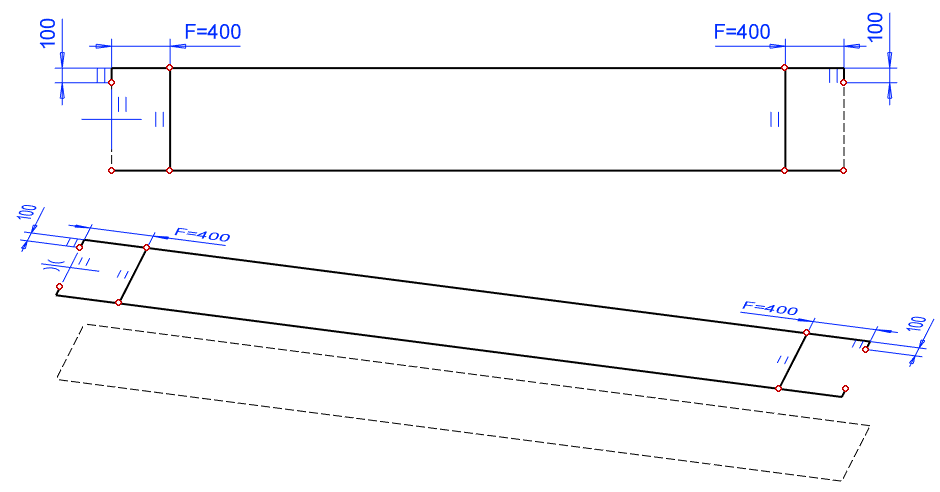
Sketch the guide lines for the plate of the feet
-
Right-click function: New Sketch > To horizontal (XY) plane.
-
Sketch a rectange.
-
Line style: Shape.
-
-
Change the style of long lines to a construction line.
-
Add symmetry and distance constraints.
-
The length of the short line (= length of plate): 160.
-
Line protrusion: 20.
-
-
OK.
Operation:
-
Guide curve.
Exit from part to assembly
-
OK.
Add plates of feet and end plates
-
Right-click function: Add > Profile.
-
Select the profile from the library Profiles > Hotrolled >FB.
-
Select size: EFB10x90, for plates of feet. (2 pcs).
-
Select size: EFB10x100, for end of rails. (4 psc).
-
-
Switch to trimming mode on the: Don't trim automatically.

-
Position the profile cross section correctly (Attachment point at the corner.)
-
If necessary, F8 allows the attachment point to be changed.
-
If necessary, F9 allows the profile to be mirrored.
-
If necessary, the right arrow and the left arrow keys rotate the profile.
-
-
Click the guide lines to add a profile.
-
Press
Trim U-profiles to plates
-
Click the profile you want to trim.
-
Click the arrow that appears at the end of the profile.
-
Click on the target face.
Create a trim:
-
For both feet. (2 pcs).
-
At both ends on both rails. (4 psc).
Solve the assembly
Since the underlying parts of the pattern have changed, solve the assembly.
-
Right-click function: Solve.
-
The program drives the model through history, changing the length of all legs.
-
Add the foot plates to the pattern
-
Click on each foot of the disk (remember Ctrl-key).
-
Right-click function: Pattern.
-
Change the Location from New pattern to Part from pattern.
-
OK.
Update a drawing
-
Open the drawing.
-
The drawing updates itself.
-
-
Remove length dimension (which tells the length of the rail).
-
Add the required dimensions.
-
Add part numbers.
Save the drawing
-
File > Save or click
Save the model
-
File > Save or click
Download the simber model (VXEN_PROF8.vxz) here.
Download here the model with end plates (VX_PROF8B.vxz)