

Exercise 7. Save the cross section to the profile library
This exercise was carried out with version 28.0 (Vertex 2022).
In this exercise you will learn to
-
Create your own profile and save it to your library.
-
Add dimension variables and a dimension table to the profile.
-
To add rendering material to the profile cross-section that will appear in the final profile.
-
To add a density to the cross section of the profile to help calculate the weight of the profile.
Functions to be used:
-
Sketching: Two-point rectangle, two point line, polyline, offset line, and Round.
-
Sketching: Symmetry, coincident, angle and dimension constraints.
-
Operation: Cross Section.
-
Dimension table.
-
Save to Library > As Profile.
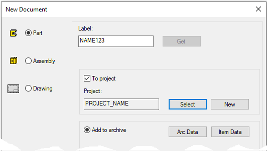
Create a new part
-
File > New > Part.
-
Enter the label (which is also the name of the model and by default will be the name of the drawing).
-
Enter the archive information by clicking Arc.Data.
-
Select the project where the model will be saved.
-
OK.
-
-
The model may have only one history stage, ie one sketch.
-
The sketch must be made in the horizontal (XY) plane.
-
No handle is added to a part, such as to features or components to be libraryed.
Note that the default placement point for the libraryed cross section is the origo of the sketch.
-
The placement point can be changed when the profile is added.
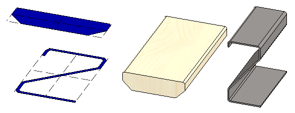
Create the only sketch of the part
A rectangle and guide lines are needed in order to indicate the point of attachment at the corners and in the middle of the cross-section when the profile is added, even if the the point would not be the actual point of the profile. For example, in this profile there are roundings at the top and bevels at the bottom.
-
Right-click function: New Sketch > To horizontal (XY) plane.
-
Sketch a two point rectangle.
-
Select a line style: Guide Line.
-
Start by clicking to the origo.
-
-
Sketch the two-point lines.
-
Use the centers of the lines in the rectangle as the start and end points of the line.
-
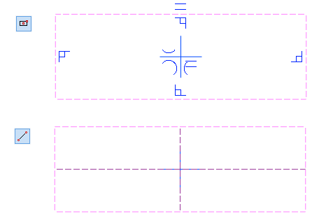
The default placement point for a profile cross-section is at the origo of the sketch, so it is a good idea to model the sketch so that in most cases the placement point does not need to be changed when the profile is added.
-
This is also affected by how the guide curves are created.
-
In particular, symmetrical profiles should be created so that the cross-section of the profile is symmetrical around the central cross.
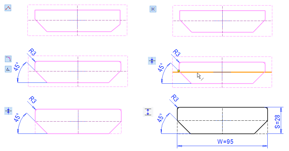
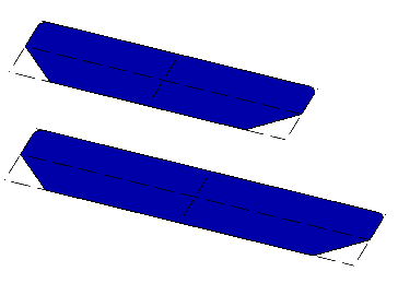
Sketch the Cross Section
-
Right-click function: New Sketch > To vertical (XZ) plane.
-
Sketch a polyline.
-
Select a line style: Shape line.
-
First, sketch it clearly smaller than the area bounded by the guide line. This makes it easier to add roundings to the corners of the lines.
-
-
Add symmetry constraints between the vertical lines and the vertical line of the center cross. Likewise for oblique lines.
-
Add Rounding to the top corners: 3.
-
Add a coincident constraint between the top end point of the oblique line and the middle horizontal guide line.
-
Add a coincident constraints:
-
The top shape line coincides with the top guide line.
-
The lowest shape line coincides with the lowest guide line.
-
The left vertical shape line coincides with the left guide line.
-
-
Stop entering constraints (Esc, V, or Middle Mouse button).
Drag lines of the sketch. The cross-sectional shapes should be maintained even if the dimensions change.
-
If the shape is not maintained, add the necessary constraints to stabilize the sketch.
Finally, add the main dimensions and enter the name of the variable in the formula field as well.
-
For width 95 and W.
-
For thickness 28 and S.
Go from sketch to operation: OK
Operation:
-
Cross Section.
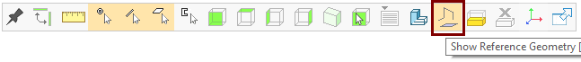
Use the G key or the corresponding function on the toolbar to display the auxiliary geometry (guide lines, auxiliary planes and cross sections):
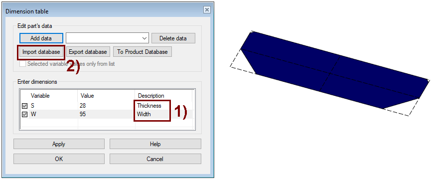
Add a dimension table for the cross section
-
Right-click function: Dimension Table.
-
The dimension table should show two rows S and W.
-
If the rows do not appear, change the sketch and add the above values to the dimensions in the Formula field.
-
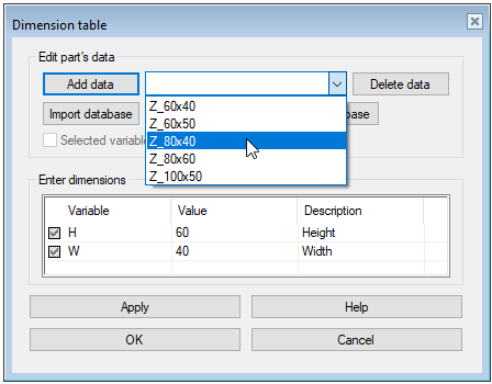
Dimension table
-
Enter the information in the Description column if the variable name is not sufficient.
-
In the top field, enter the profile size name or ID that appears in the assembly feature tree and parts list.
-
For example, 95x28 or TerraceBoard_95x28.
-
-
Press Add data.
-
Enter another name in the top field (120x28 or TerraceBoard_120x28).
-
Enter a new value for variable W (Widh): 120.
-
Press Add data.
-
Save the data in the dimension table: with the OK button.
Test the dimension table
-
Right-click function: Dimension Table.
-
Select a size from the top row.
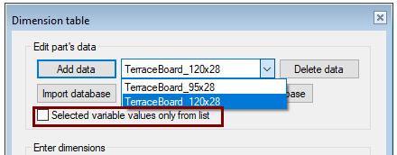
If you select Selected variable values only from list, then you can select only the values in the dimension table for the profile retrieved from the library.
-
If there is no selection, feel free to enter the new values when adding the profile.
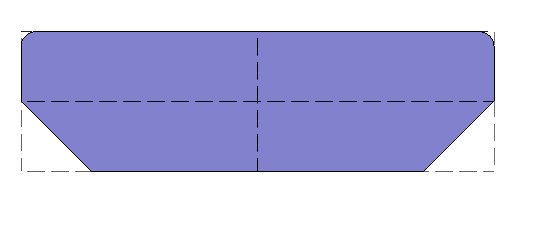
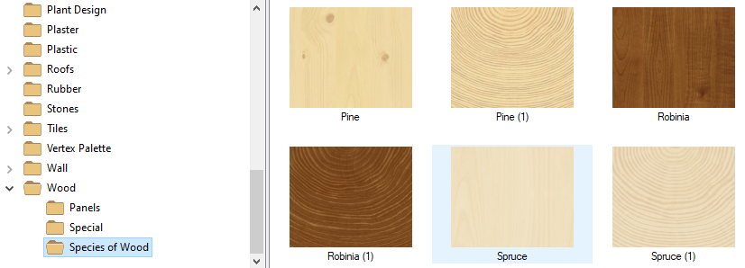
Add rendering material
When rendering material is saved for a cross section, the profile receives the same visualization material.
-
Right-click function: Rendering > Chance material.
-
Press Browse.
-
Find the rendering material: Wood > Species of wood and double-click, e.g. Spruce.
-
In the Edit Rendering Material dialog box, accept the defaults by pressing the OK button.
-
In the Change Rendering Material dialog box, accept the defaults by pressing the OK button.
Unless you add rendering material to the cross section before saving to the library, so the profile is gray and its rendering material is STEEL.
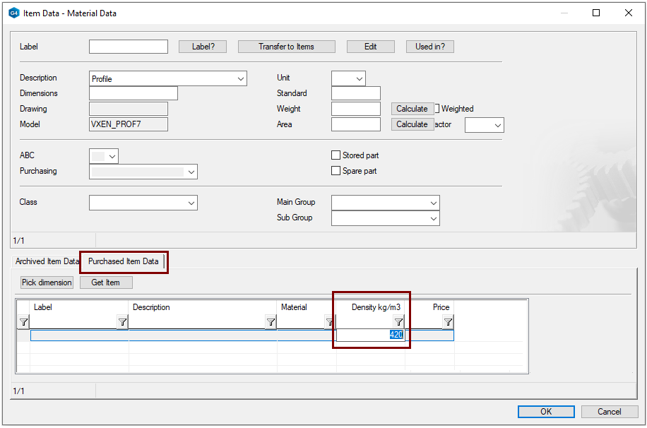
Enter the material or density
If the prolile is something other than the default material (Steel 7850 kg/m3), then it is advisable to give at least the density of the raw material in the item data for the cross section so that the calculation of the model weight gives correct results.
-
Right-click function: Item Data.
-
Move the cursor to the line at the bottom of the dialog and take a right-click function: Add row after.
-
Select the: Purchase Item Data tab.
-
Enter in the Dencity field, eg spruce density: 420.
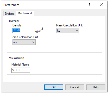
The default material is the same for all designers who use Vertex G4 installed on the same file-server.
You can adjust it:
-
File > System Preferences > Mechanical Engineering > Mechanical-tab > Density.
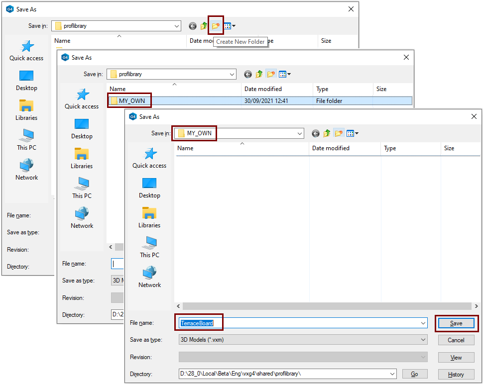
Save the cross section to the profile library
-
Right-click function: Save to Library > As Profile.
-
Select an existing library or create a new one.
-
Enter a file name for the profile.
-
Save.
Save the model
-
File > Save or click


Create a new part
-
File > New > Part.
-
Enter the label (which is also the name of the model and by default will be the name of the drawing).
-
Enter the archive information by clicking Arc.Data.
-
Accept current or select the project where the model will be saved.
-
OK.
-
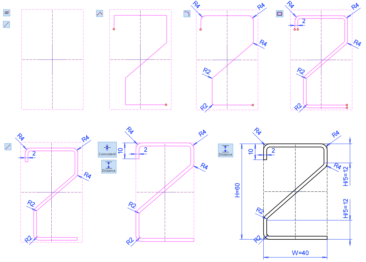
Sketch the Cross Section
-
Right-click function: New Sketch > To horizontal (XY) plane.
-
Sketch a two point rectangle.
-
Sketch the two-point lines.
-
Sketch a polyline.
-
Use the Offset function to add a parallel line.
-
Close the shape of the ends by drawing a two-point line on the ends.
-
Add dimensions and formulas.
-
H (Height)
-
H/5
-
W (Width)
-
-
Try variation already in the sketch using a dimension table.
-
Right-click function: Dimension Table.
-
Enter new values for the width and height (initially moderate values).
-
Operation:
-
Cross Section.
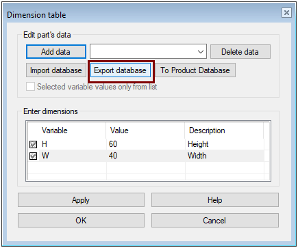
Use Excel to add rows to dimension table
-
Right-click function: Dimension Table.
-
Enter the information in the Description column if needed.
-
Click the Export database.
-
The program provides a file name dimtable and a directory of the Vertex model (picts or project folder) as the storage location.
-
-
Accept the name with OK or, if necessary, save them somewhere else under another name.
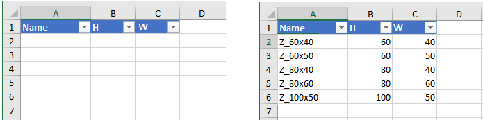
Enter the dimension table data in Excel
-
Excel may warn or prevent you from opening the dimension table.
-
You have to allow in Excel processing macros so that Vertex can send an editable file in Excel.
-
-
Fill in the Name and Dimension fields.
-
Save the Excel file.
-
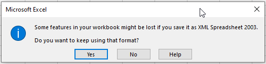
You may receive the following warning, which you can acknowledge by pressing Yes.
-
Import a dimension table edited in Excel into a dimension table for a part
-
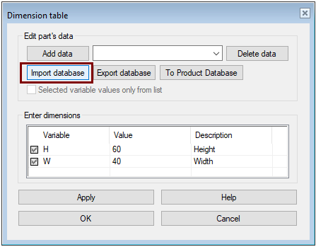
Right-click function: Dimension Table (If the dimension table is not already open).
-
Click the Import Database.
-
The program suggests importing a dimtable file. Read it or retrieve a file you previously saved.
-
The program confirms the import of the database:
-
Click OK to exit the Dimension Table dialog box, because the rows in the dimension table will not appear until the next time you open the dimension table.
Test the dimension table
-
Right-click function: Dimension Table.
-
Use the preselection button to search for rows.
-
Click the Apply.
Save the cross section to the profile library
-
Right-click function: Save to Library > As Profile.
-
Select an existing library or create a new one.
-
Enter a file name for the profile.
-
Save.
Try adding your profile to the assembly.
-
Create a new assembly.
-
Create a local part there: SKELETON, where you draw the guide geometry. (However, you can also drag a profile from point to point, so you can also skip creating a local part of guide curve .
-
Add profiles to the assembly.
-
Note that your own profiles can be found in the library: Profiles> Own... .
-
Be sure to refresh your browser to see the profiles you just added.
-
Save the model
-
File > Save or click
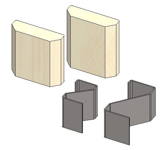
Download the terrace board model here (VX_PROF7.vxz)
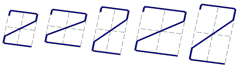
Download the Z-profile model here (VX_PROF7B.vxz)