

Exercise 7: Modeling in an assembly
This exercise was carried out with version 27.0 (Vertex 2021).
In this exercise you will learn to
-
Take advantage of the geometry of the second part when sketching a new part.
-
To place a sketch on the face of another part.
-
To add a cutout thread feature and also copies of it.
-
Make a feature pattern and locate it using constraints.
-
To create the drawing so that the front and top directions are clicked from the model.
-
To understand why some parts appear in blue in the feature tree of the assembly model.
Functions to be used:
-
File > New > Assembly.
-
Drag the part in another file format directly into the assembly.
-
File > New > Part.
-
New Sketch > To Ref. Reometry > Face.
-
Sketch: Copy lines (from the other part to the sketch plane).
-
Sketch: Add constraints, e.g. Coincident, symmetry, distance and centering constraints.
-
Library feature > Cutout > Thread > feature and copy of it.
-
Drawing > New.
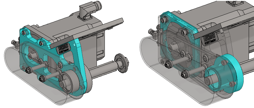
Below is the Suhner WEP 100, as presented on the Traceparts website (https://www.traceparts.com) and from which you can download it in various file formats.
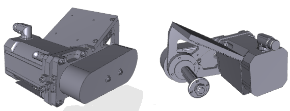
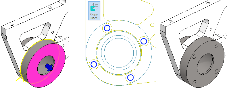
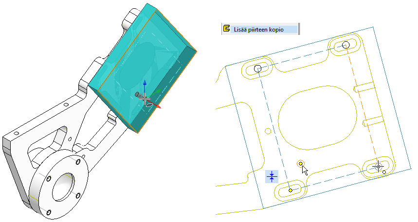
As a starting point, we use the part shown in blue on the left figure, which we add into the assembly. In this exercise, we will model the parts shown in blue in the figure on the right using the imported part.
Get a project that includes the necessary parts
-
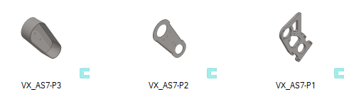
Download the zipped Vertex project (VX_AS7_PARTS.vxz) here.
-
Drag the file from the downloads section of your Internet browser onto Vertex G4.
-
Be sure the models are found (in browser B) in project VX_COURSE_ASSY.
-
If necessary, refresh your browser, if those models VX_AS7-P* are not found immediately.
-
When you use the Export function in the Projects group on the Archives tab, Vertex compresses all the files and subfolders under the directory, as well as extracts from the model, drawing, and project archives.
-
Files other than those displayed in the Vertex browser may be included.
-
For example, memos and models and drawings in other file formats.
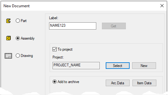
Create a new assembly
-
File > New > Assembly.
-
Enter the label (which is also the name of the model and by default will be the name of the drawing).
-
Enter the archive information by clicking Arc.Data.
-
Select the project where the model will be saved.
-
OK.
-
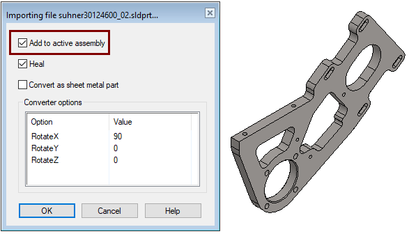
Import the part
-
Drag the file Suhner30124600_02.SLDPRT from the Vertex G4 project directory
shared\projects\VX_COURSE_ASSY
on the Vertex G4 onto the assembly opened above.
-
Import file XXX dialog is opened.
-
-
Select: Add to active assembly and Heal.
-
OK.
-
Drop the part into place with


Or if you don't have a Solidworks compiler available, then
-
Add the part VX_AS7-P1 in the assembly from VX_COURSE_ASSY project, where that SW model has already been converted into Vertex G4 format.
With the function: File>Import you can read eg *.sat, *.stp and *.igs-, *.SLDPRT, *.SLDASM files into Vertex, provided that you have the compiler in question.
-
You can save such a model to the archive after it has been imported (normally in its own window).
-
If you only need a model in one assembly, you can import it directly into the assembly, as long as:
-
The Vertex desktop has an active assembly model.
-
In the import dialog, select the option: Add to active assembly.
-
Sleeve modeling
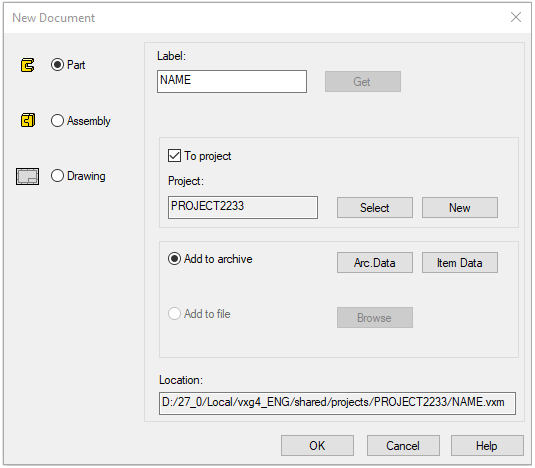
Create a new part (Sleeve) in the assembly
-
Right-click function: New > Part.
-
Enter the label (which is also the name of the model and by default will be the name of the drawing).
-
Enter the archive information by clicking Arc.Data.
-
Select the project where the model will be saved.
-
OK.
-
-
The program switches from assembly to part mode.
Sketch a part on the face of another part
-
Right-click function: New Sketch > To Ref. Reometry > Face.
-
Click on the face.
-
The program enters sketch mode.
-
And flips the sketch perpendicularly if the setting Perpendicular is selected in the Settings group on the Sketch tab).
-
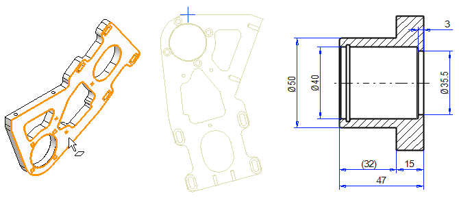
On the right is a cross-section of the sleeve, which will show the dimensions needed for the exercise later.
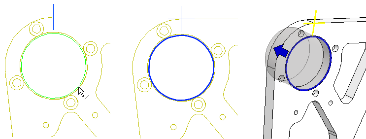
Model the first feature
-
Right-click function: Line > Copy to sketch Plane.
-
Select the cylinder line from the frame.
-
OK or middle mouse button or copy the selected lines to the sketch plane.
-
Operation: Boss - Extrude, Flip the direction.
-
Length: 32.
-
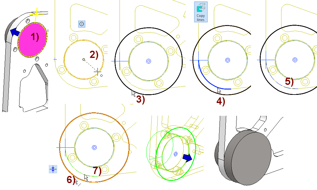
Create the second feature
-
Select the face, in the figure 1) and the Right-click function: New Sketch > Face.
-
Sketch a circle with two points, click the center point from the center of the cylinder, in the figure 2), and click the perimeter point, in the figure 3).
-
Copy the curved line of the corner from the other part, in the figure 4) with the Copy Lines function.
-
Change the copied line style to a contruction line, in the figure 5). Select the line and function: Properties or the Construction Line from the Style.
-
Add the coincident constraint between the circle you sketch and the arc copied from another part, in figures 6) and 7).
-
Operation: Boss - Extrude
-
Length: 15.
-
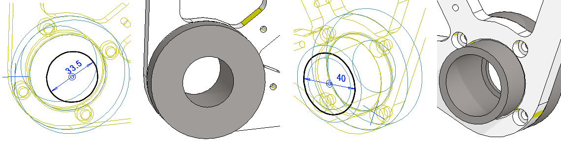
Create the main hole of the sleeve in two steps
-
Sketch a smaller circle at the larger end 33.5.
-
Operation: Cutout - Extrude - Thru All.
-
-
Sketch the smaller end of the larger circle 40.
-
Operation: Cutout - Extrude - Thru All.
-
Create the locations of the threaded holes in the sleeve
-
Sketch Plane: On the end face of a larger cylinder.
-
Copy small circles from the second part, with the Copy Lines function.
-
Operation: Guide Curve.
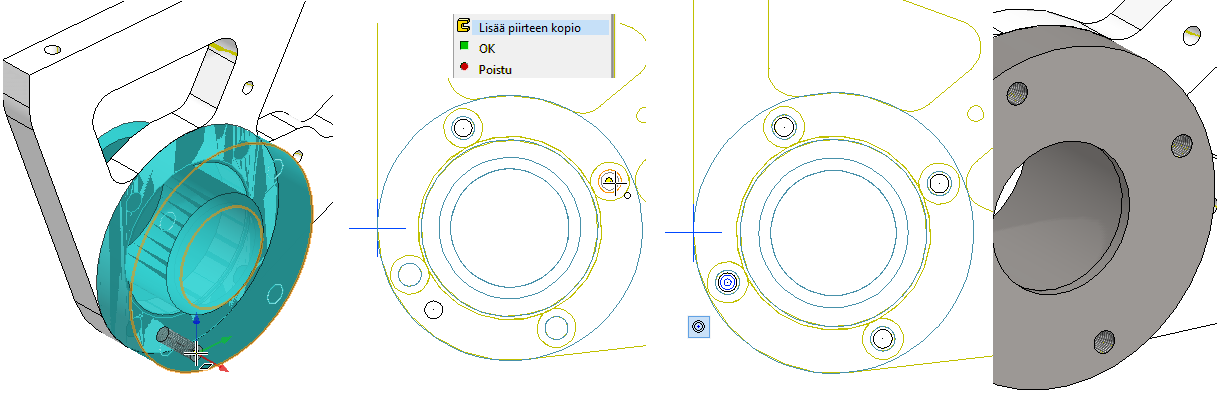
Create the threaded holes in the sleeve
Add threaded holes to the model at the location indicated by the Guide curves.
-
Right-click function: Library feature > Cutout or function Add cutout using feature from library from Library Feature group in Part tab.
-
Select a feature: (Libraries > Features > Standards>) Threads > Metric > through_all.
-
Select size: M6.
-
Enter h (length): 15 and TL (Thread length): 15.
-
-
Click to the location of the first feature on the end face (the cursor does not respond to the center of the guide line).
-
Right-click function: Add Feature Copy.
-
To add a copy three times, click to the center of the guide line circle.
-
-
Finally, place the first feature concentric with the guide line circle.
-
OK.
Additional task of part modeling
-
Finish the inside corner of the sleeve with rounding: 0.6 mm.
-
Add a chamfer to the head: 1mm 30°
-
Add the Cirlip groove: D 42.5, width 1.9 and distance to the end 4.
Mounting plate modeling
Exit the sleeve model and make a new part (mounting plate)
-
Exit from part mode to assembly: OK. (This also save the part-file).
-
Right-click function: New > Part.
-
Enter the label (which is also the name of the model and by default will be the name of the drawing).
-
Enter the archive information by clicking Arc.Data.
-
Select the project where the model will be saved.
-
OK.
-
-
The program switches from assembly to part mode.
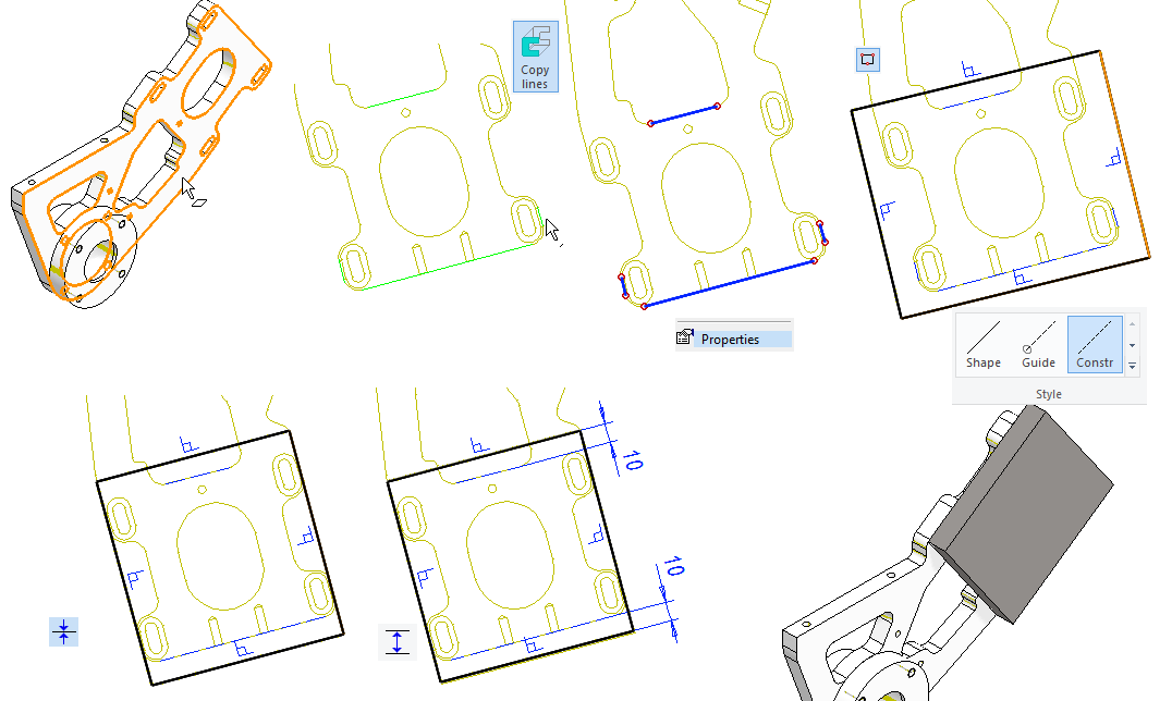
Create a mounting plate frame
-
Right-click function: New Sketch > To Ref. Reometry > Face.
-
Click on the face.
-
The program enters sketch mode.
-
-
Function: Copy Lines. Select four lines from the body.
-
Change lines to Constraint lines.
-
Roughly sketch the rectangle to the correct position. (Use the Shape style).
-
Add the coincident constraints between the short guide lines and two lines of rectangle.
-
Add the distance constraints (10) between the longer guide lines and two lines of rectangle.
-
Operation: Boss - Extrude
-
Length: 12.
-
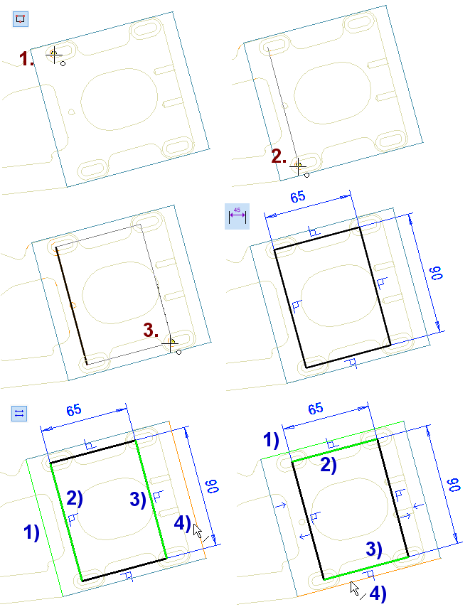
Create guide lines for threaded holes
-
Right-click function: New Sketch > Face.
-
Sketch a rectangle using the centers of the arcs of the body.
-
Points 1, 2 and 3 in the figure.
-
-
Add dimensions to the rectangle. Accept the dimensions (65 and 90).
-
Center the rectangle with two Equal distance constraints.
-
Lines 1), 2), 3) and 4) are shown in the figure.
-
-
Finally, change the line style to Guide line.
-
Operation: Guide Curve.
Create the mounting plate threaded holes for frame adjustment
Add threaded holes to the model at the location indicated by the Guide curves.
-
Function: Cut from Library feature group or Right-click function: Library feature > Cutout
-
Double-click the feature: (Libraries> Features> Standards>) Threads > Metric > through_all.
-
Select size M6.
-
Enter the length h 12 and the thread length TL 12.
-
-
Click to the location of the first feature on the end face.
-
Right-click function: Add Feature Copy.
-
Click the corner points of the guide lines to place the copy three times.
-
-
Finally, position the first feature to coincide with the last corner of the guide line.
-
OK.
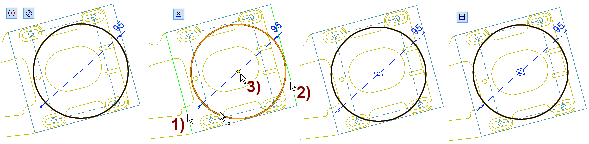
Create the center hole needed by the electric motor
-
Sketch a circle and dimension it, diameter 95.
-
You get a dimensioned circle when, after pointing to the center point, you do not point to the perimeter point, but enter a radius from the keyboard, eg 47.5 (or expression 95/2).
-
-
Position the circle in both directions in the center, using the centering constraint.
-
First, click to the borders, in the figures 1) and 2).
-
Then click to the point to be centered, in the figure 3).
-
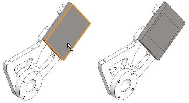
Add threaded holes for engine mounting
-
Ex. with Right-click function: Library feature > Cutout.
-
Double-click the feature: (Libraries> Features> Standards>) Threads > Metric > through_all.
-
Select size M8.
-
Enter the length h 12 and the thread length TL 12.
-
-
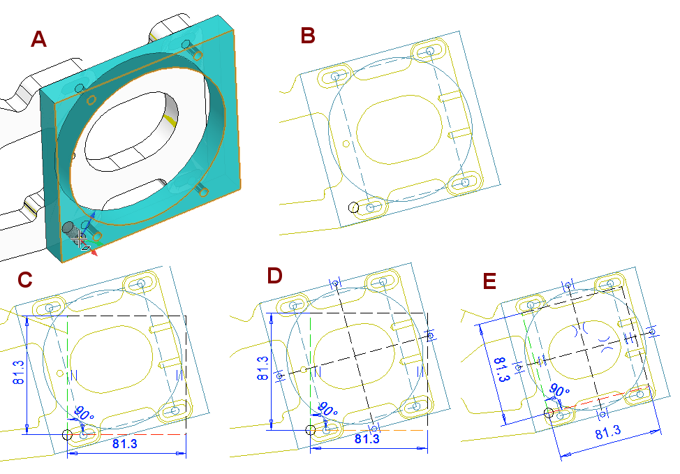
Click to the place on the correct face. In the figure A.
-
Do not position the feature, exit with OK. In the figure B.
Make a series of threaded features
-
Select a feature (From the feature tree or face of feature).
-
Right-click function: Pattern.
-
Enter the data: Length and widths: 2 pcs and spacing 81.3.
-
OK.
-
-
Click to the cursor position from the center of the hole you added earlier. In the figure C.
-
Sketch the two construction line from the center to the center of the edges of the mounting plates. In the figure D.
-
For pattern construction lines, add symmetry constraints to the centerlines sketch above. In the figure E.
Additional task
-
Add 10 * 10 chamfers to the corners.
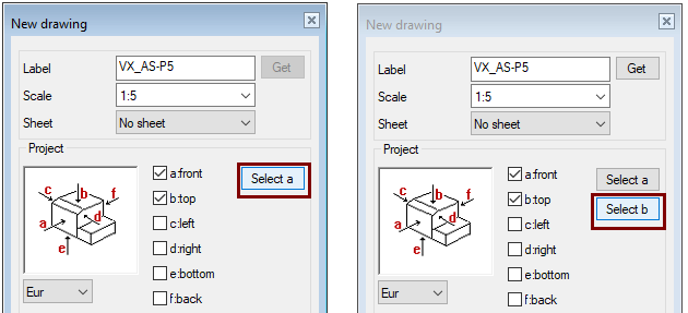
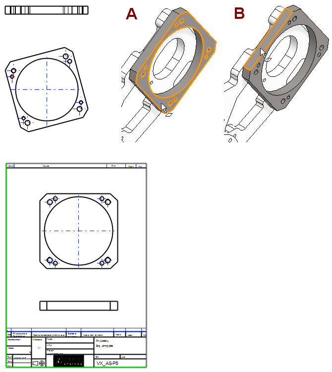
Create a drawing on the mounting plate
If you make a new drawing and take projections from the front and top of it, you will get the projections shown on the left in the figure. This is due to the position of the model.
-
Click Drawings from the feature tree.
-
Right-click function: New Drawing.
-
Press Select a.
-
Click to the face of the part, in the figure 1).
-
Press Select b.
-
Click to the face of the part, in the figure 2).
-
Scale: 1:1.
-
Sheet: A3.
-
Deselect: Auxiliary geometry and Hidden lines.
-
OK.
-
If the part or assembly is in a vague position, then it is advisable to create the drawing by clicking the front projection and, if necessary, the top projection of the model.
-
The Click b button appears after you have clicked to the face for front projection.
Save the drawing of part and return to the assembly
-
Save the drawing and remove it from the Vertex desktop.
-
Press OK to exit the part to be edited to the assembly.
When you look at the feature tree of the assembly, you will see that name of the sleeve and mounting plate are blue.
-
This means that these parts have interfaces with the geometry of other parts.
-
At worst, it means that these parts should not be modified, as in this same assembly, as the "sketch geometry attached to other parts" may behave badly in some cases, especially if the history of the part is repeated.
If you select the part you are creating, you will see that there are coincident constraints in the list of constraints , even if you have not added any.
-
These constraints arise e.g. when add a sketch of a part on the face of another part. (New Sketch > To Ref. Geometry > Face / Line / Plane by 3 Points).

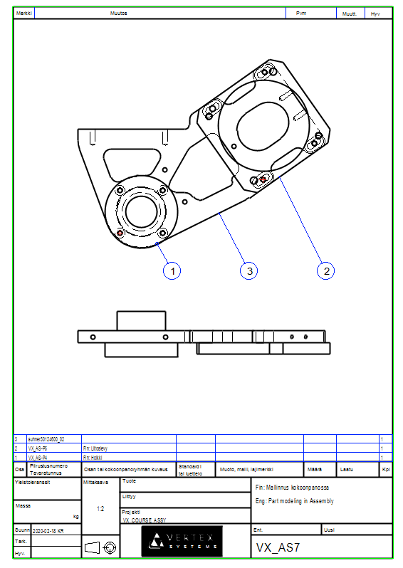
Create a drawing for the model
For more detailed instructions, see the Modeling parts course exercise 5 Drawing of Model.
Save the model
-
File > Save or click


Download the finished assembly model (VX_AS7.vxz) with parts here