

Exercise 7: Eye Screw
This exercise was carried out with version 27.0 (Vertex 2021).
In this exercise you will learn to
-
Create a part using a guide curve and cross section.
-
Add a thread mark that appears in the drawing as a dimensioned thread and in the model as a visual image.
-
Add a chamfer to the edge.
Functions to be used:
-
We review sketching tools.
-
Operation: Guode curve and Cross Section.
-
Sweep > Boss.
-
Thread symbol.
-
Bevel.
-
Item Data.
-
Drawing > New Drawing.
Create a new part
-
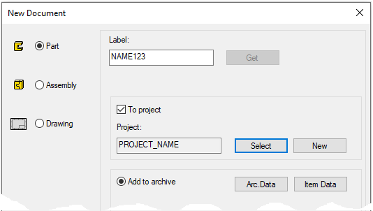
File > New > Part.
-
Enter the label (which is also the name of the model and by default will be the name of the drawing).
-
Enter the archive information by clicking Arc.Data.
-
Select the project for the model.
-
OK.
-
Create the first feature
-
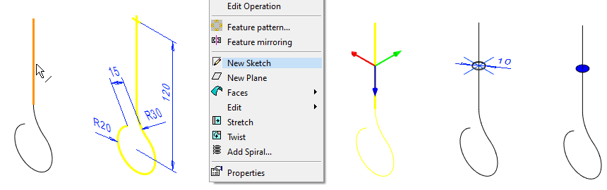
New Sketch > To vertical (XZ) plane
Sketch the shape
-
Use the Smart (Smart line chain) function, for example.
-
Start sketching from the origo so that the cursor also catches the vertical line in the center cross.
-
-
Add a coincident constraint between the vertical line and the center point of the lower arc.
-
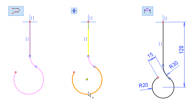
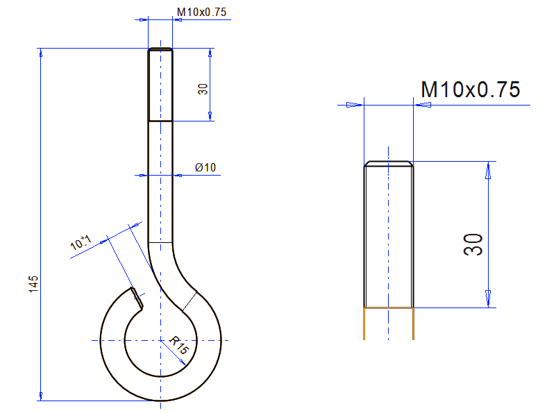
Dimension according to the figure.
-
Dimension 15 is defined between the upper arc and the end point of lower arc.
-
If the addition of dimension (15) does not seem to be successful, first drag the end of the arc to a suitable distance.
-
-

Operation
-
Guode Curve.
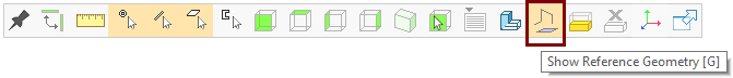
You can display the auxiliary geometry (guide lines, auxiliary planes and cross sections) with the G key or the Show Reference Geometry function of the Tool Strip:
Create the cross section
-
Select a line (e.g. a straight line).
-
Right-click function: New Sketch.
-
The program opens a dialog that allows you to adjust the position of the sketch.
-
Accept the default (Relative position and value 0.5) so that the sketch plane will be in the middle of the line.
-
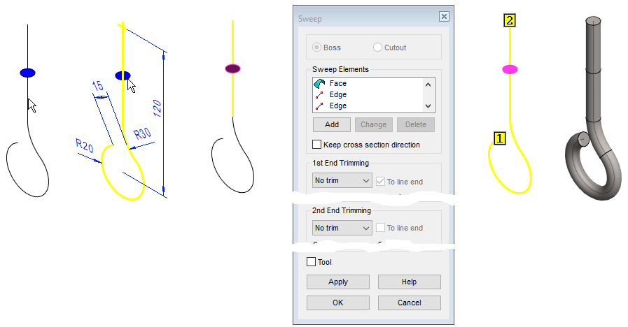
Sketch the shape
-
The function: Circle. (Circle with Center and Radii Point).
-
Place the center point at the origo of the sketch.
-
Add a Diameter constraint: 10.
-
Operation
-
Cross Section.
See the sketch placement on the line for more details:
-
Sketching course - in modeling of part
-
9. Seal.
-
Paragraph: Create a sketch for the guide curve.
Create a part of the cross section and control curve
-
Select line.
-
Select cross section (Remember the Ctrl key).Right-click function:
-
Right-click function: Sweep > Boss.
-
Accept the sweep dialog defaults (no trimming).
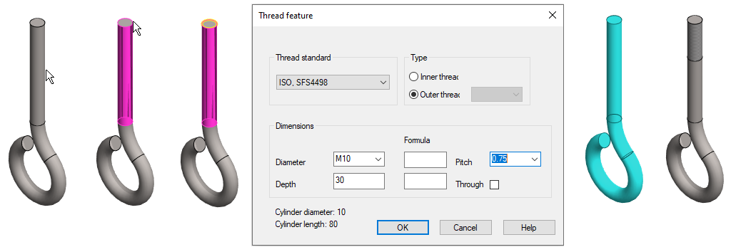
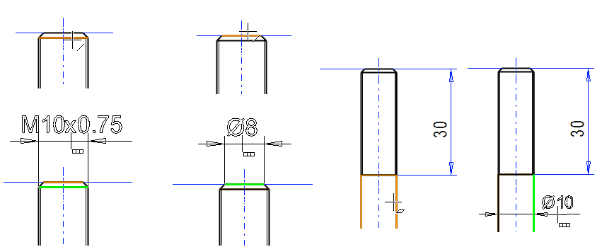
Add a Thread Symbol
-
Click to the cylindrical surface on which you want to add a Thread Symbol.
-
Click to the line where the thread symbol begins.
-
The Thread feature dialog opens.
-
Default thread standard ISO, SFS44498 (mm threads).
-
The program can suggest an Outer thread for the pin and an inner thread for the hole as the Type.
-
The dialog tells you the diameter and length of the cylinder surface.
-
-
Select Diameter: M10.
-
Enter Depth: 30.
-
Select Pitch: 0.75.
-
OK.
The thread mark feature appears in the drawing where the thread can be dimensioned, but it does not make a real thread to the model to ensure fast program operation in assembly with many threaded parts.
-
Real threads must be modeled separately using a spiral and a thread-forming cross section.
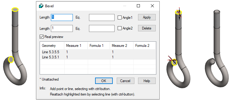
Add bevels
-
Select a line at both ends of the part (Remember the Ctrl key).
-
Right-click function: Add Round/Bevel > Single Edge Bevel.
-
Enter the bevel length dimensions: 1 and 1.
-
OK.
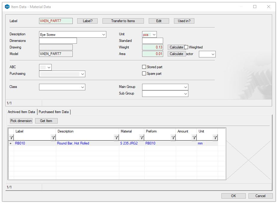
Give item data to the part
-
Right-click function: Item Data.
-
Press: Get Item.
-
Press the preselection button in the Main Group field.
-
Select: Steel
-
Select: Bars
-
Select: Hot Rolled Round bar
-
OK.
-
Select: RB010 or some other suitable item (by double click).
-
-
Also fill in part information, e.g. weight.
-
Press: Calculate.
-
-
OK.
Create a drawing for the part
-
See more detailed instructions for the exercise: 5. Drawing of the model.
-
Drawing > New Drawing (In the feature tree).
-
A couple of notes about the drawing:
-
In order to dimension the tolerated dimension 10 + -1, a guide line must be drawn at between the ends of the chamfers.
-
Because a line is projected on the drawing that is not a valid other part to the dimension.
-
The M10x0.75 dimension is obtained when the line at the end of the helical feature is clicked in the dimensioning.
-
diameter 10 dimension is obtained when a cylinder is clicked.
Save the drawing
-
File > Save or click


Save the model
-
File > Save or click