

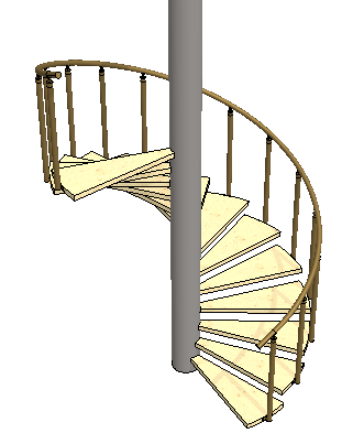
Exercise 6: Pattern and edit a part
This exercise was carried out with version 27.0 (Vertex 2021).
In this exercise you will learn to
-
To create a polar pattern with ascents.
-
Editing the part model and updating it to the assembly.
-
To measure distances from a model.
-
To add a perspective projection of the model to the drawing.
-
To cut off unnecessary geometry from the projection of the drawing.
-
To hide the part so that it does not appear in the drawing.
-
Adjust the pixel resolution of a rendered projection.
Functions to be used:
-
Add > Model, Add > Model (And create a pattern at the same time).
-
Constraints: Concentricity and Parallel.
-
Edit (Part, Assembly).
-
Part properties: Not To Assembly Drawing.
-
In an Assembly: Update All.
-
Distance.
-
Drawing: Cut View.
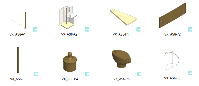
Get a project that includes the necessary parts
-
Download the zipped Vertex project (VX_AS6_PARTS.vxz) here.
-
Drag the file from the downloads section of your Internet browser onto Vertex G4.
-
Be sure the models are found (in browser B) in project VX_COURSE_ASSY.
-
If necessary, refresh your browser, if those models VX_AS6* are not found immediately.
-
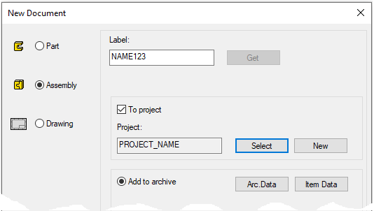
Create a new assembly
-
File > New > Assembly.
-
Enter the label (which is also the name of the model and by default will be the name of the drawing).
-
Enter the archive information by clicking Arc.Data.
-
Select the project where the model will be saved.
-
OK.
-
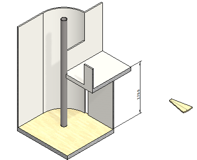
Add a piece of building (props) to the assembly
-
Add building props (VX_AS6-A2). (from project VX_COURCE_ASSY).
-
Right-click function: Add > Model.
-
or

-
Drop the building props (VX_AS6-A2)
into place with


-
-
Add a step (VX_AS6-P1) and point to its location in space.
-
Press

If you are planning stairs, check the information on official building regulations. Information from various sources has been collected below. The information is only used to do this exercise.
-
In this exercise, progress is ignore.
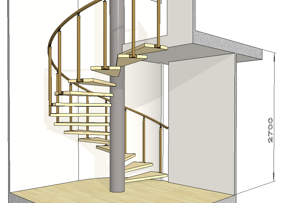
In this exercise, the floor height is 2700mm
-
If there were 14 steps, then the step height is 180mm
-
If there were 15 steps, then the step height is 168.75mm
-
If there were 16 steps, then the step height is 158.82mm
One piece of information is about a spiral staircase:
-
The step height had to be 160 .. 220mm
-
The normal step height is 170 .. 180mm
Place the first step on the frame post
-
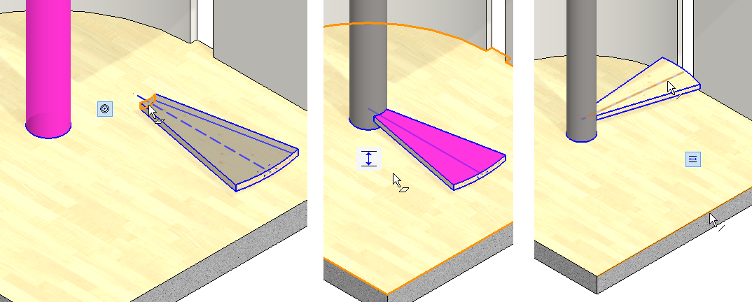
Add a concentricity constraint between the cylindrical face of the frame post and the inner cylindrical face of the step.
-
Add a distance constraint between the floor surface and the top surface of the step: 180.
-
Add a parallel constraint between the guide line of step's bottom and the floor edge line.
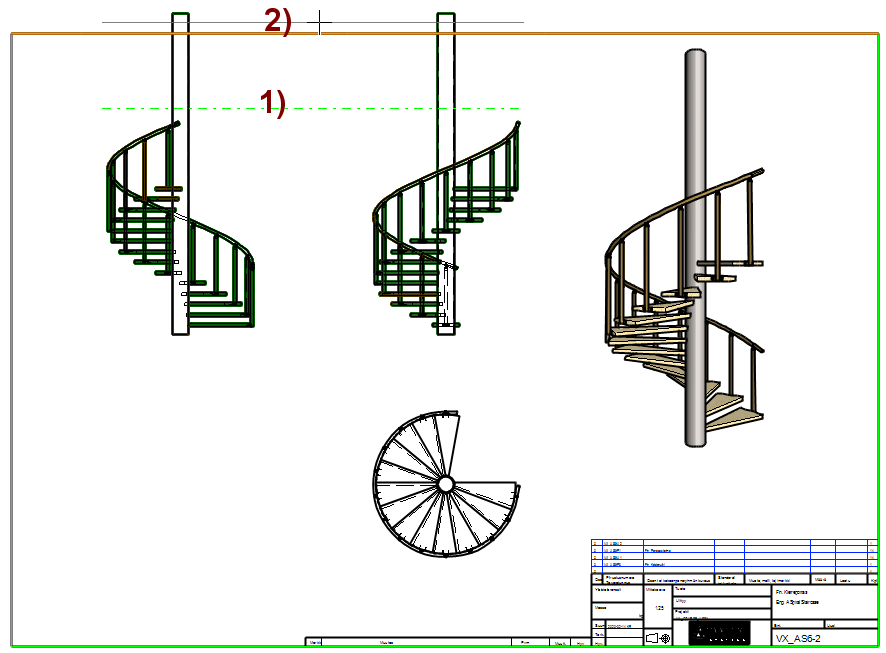
Create a pattern of steps
-
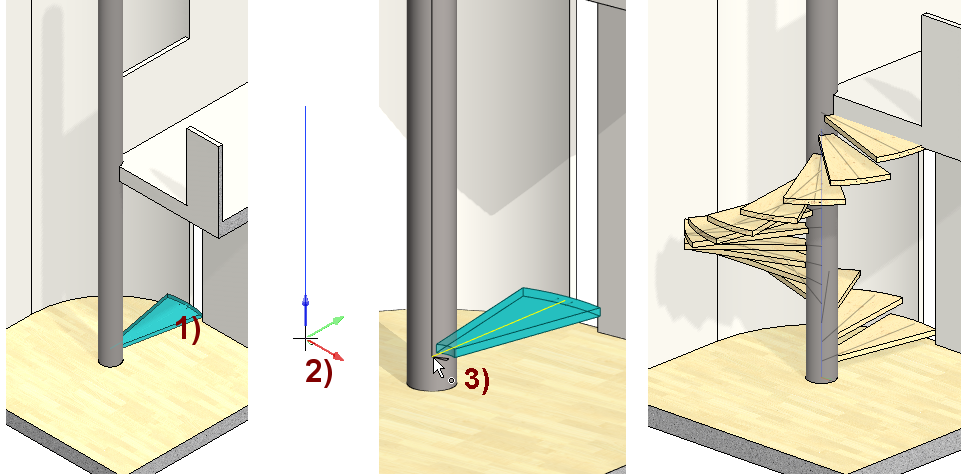
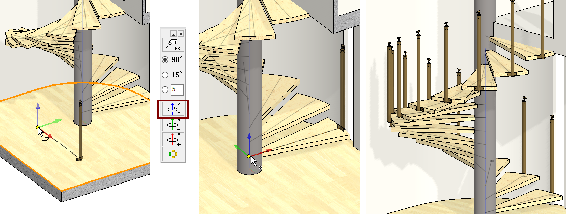
Click to the step, in the figure 1).
-
Right-click function: Pattern.
-
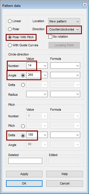
Enter the pattern information:
-
Select Direction: Counterclockwice.
-
Select: Polar With Pitch.
-
Enter Number (of steps): 14
-
Enter an angle (initially 260 °), ie 3/4 of a full turn, roughly removing half of the step angle.
-
Enter Pitch Delta: 180. (2700/15=180, so 14 steps meens 15 climbs)
-
OK.
-
-
The program draws an auxiliary geometry to determine the position and direction of the series, in the figure 2).
-
Click the position of the auxiliary geometry at the guide line end of step, in the figure 3).
View the relative position of the spiral staircase steps
-
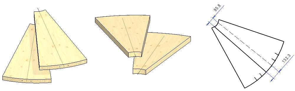
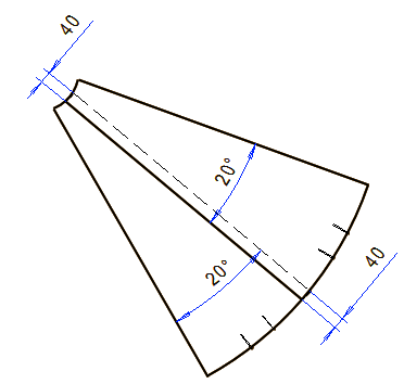
Visually, the step will overlap too much, so the dimensions of the step could be changed.
-
If you want accurate information, make a drawing of two overlapping steps.
-
Create a new configuration first.
-
Choose two steps.
-
Right-click function: Hiding > Hide Others.
-
Drawings > New Drawing. (but the drawing should not be saved)
-
Scale 1:10 ... 1:20.
-
With Hidden lines.
-
-
There are 14 steps, so there is one less rotation, i.e. 13, and they are tentatively placed at an angle of 260°, so the average rotation between the steps is 20°
Edit the geometry of the step
-
Click a step (VX_AS6-P1).
-
Right-click function: Open model.
-
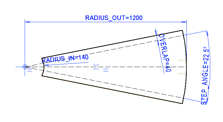
Take a look at the first sketch of the step. (Edit from sketch)
-
You will see the values that affect the Dimension table.
-
Exit sketch (OK).
-
-
Right-click function: Dimension Table.
-
Change the value of STEP_ANGELE from 22.5 to 20.
-
Change the OVERLAP value from 40 to 20.
-
-
Save the step (VX_AS6-P1).
Change the window activity to the assembly window (for example, using the Ctrl Tab keystroke or the List function in the Window group of the View tab).
-
Press the F5 and the program will mark the models to be updated (steps) in red.
-
Right-click function: Update All.
As a result of these changes, the steps overlap by 40 mm.
The top step of the model goes inside the middle floor of the building, that 20 mm, so it should be made into a separate model of its own.
-
But in this exercise it is not done.
Add handrail post assembly
-
Add the handrail assembly (VX_AS6-A1).
-
Rotate the assembly 90° around the blue Z axis before clicking the location.
-
Click to the location (in the middle figure) of the point where the end of the step guide line is attached.
-
The program asks: Create pattern?
-
Answer: Yes.
Try repositioning the part.
Or add the handrail to the assembly and place it in a step.
-
Concentricity with respect to the cylindrical face of the outer edge of the step and the (cylindrical) inner face of the mounting plate of the handrail post and with the concentricity of the mounting holes.
-
Select the assembly of handrail post (you can select all parts of the subassembly at once from the feature tree).
-
Right-click function: Pattern.
-
Location: Part from pattern.
-
Then click the step.
-
OK.
There are regulations regarding the distance between the vertical posts of stair railings.
A vertical post according to this exercise alone is not enough to cover these provisions, but the post should have, for example, auxiliary posts, so that no gap exceeds 100 mm.
Adding and editing a handrail.
-
The spiral-shaped handrail is modeled by drawing auxiliary geometries. You can look the model by reading the model VX_AS6-P6.
-
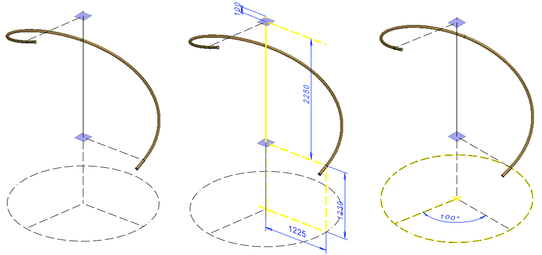
The dimensioning and positioning of the model is designed so that the steering curve circle comes to the floor level and
-
The spiral guide curve (Shape line) determines the slope between the first and last handrail post.
-
The angle shown at the bottom (Figure 100 and Model 101.25) determines the rotation of the stairs by 260 degrees.
-
The modeling has been carried out with a sweep made using a guide curve and a cross-section, which has since been extended at both ends with a draft feature.
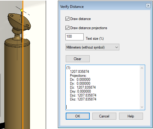
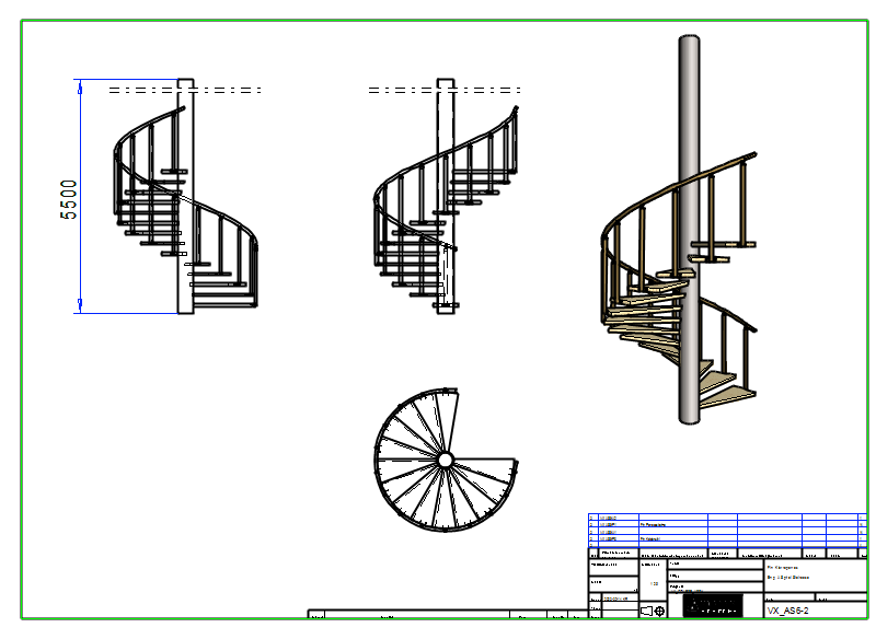
Examine the assembly model by measuring it with the Distance function
-
For example, the vertical distance between the main points of the lowest and upper handrail posts is 2340.
-
The end point of the guide curve of the fastening piece at the upper end of the lowest handrail post is approx. 1208 mm from the floor, so a good guess for the height of the spiral exit end from the floor is 1210 mm
The face of the helical handrail is a spline face, so it cannot be mathematically positioned with the the handrail post wich have a cylindrical face.
Modify the handrail (VX_AS6-P6) to the above dimensions.
-
Edit the first sketch and change the dimensions.
-
1230 > 1210.
-
2250 > 2340.
-
-
Edit the second sketch and change the dimension.
-
101.25 > 100.
-
-
Save the handrail. Ctrl S.
Add the handrail to the assembly
-
Add the handrail (VX_AS6-P6).
-
Rotate the assembly 90 ° around the blue Z axis before pointing the location.
-
Click to a place (If you click to a place at the bottom of the frame post, the program suggests creating a pattern. Do not create a pattern).
We aim for a drawing that does not show the piece of the building frame, but shows the post of frame (Local Part: COLUMN).
-
This can also be achieved by creating a new configuration that hides the frame of the building and then creating a drawing for that configuration.
-
But for the sake of practice, we will move part of the sub-assembly to the main assembly.
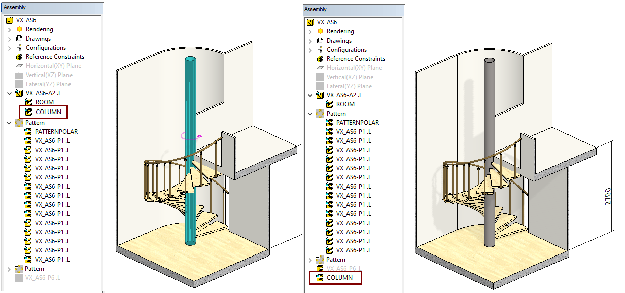
Move the frame post to main assembly
-
Select a post (COLUMN).
-
Right-click function: Other functions > Change assembly.
-
In the feature tree, click the main assembly symbol.
-
Confirm your selection with OK.
-
The program warns you that the function is irreversible.
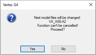
-
Confirm changer: Yes.
Edit the building assembly
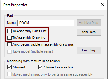
Do this because the building block would not appear on the assembly drawing
-
Select the assembly (VX_AS6-A2).
-
Right-click function: Edit.
-
Click on the frame (ROOM).
-
Right-click function: Properties
-
Deselect: To Assembly Parts Lists.
-
Deselect: To Assembly Drawing.
-
OK.
-
-
Return to main assembly: OK.
Create a drawing for the model
For more detailed instructions, see the Modeling parts course exercise 5 Drawing of Model.
-
Scale: 1:25.
-
Select projections: Front, Top, and Right.
-
Save to achive.
-
Add symbol: A2.
Activate the model window (eg Ctrl Tab).
-
Rotate it to the isometric projection you want.
-
Include Perspective View: On the View tab, select the Perspective from Projection group.
-
Rotate the model to the desired position.
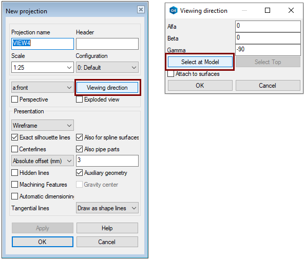
Activate the drawing window (eg Ctrl Tab).
-
Right-click function: Projection.
-
The New Projection dialog is opened.
-
-
Click: Viewing direction.
-
The Viewing direction dialog is opened.
-
-
Click: Select at Model.
-
If the view of model is valid, confirm with Ready (=
-
The Viewing direction dialog is opened.
-
-
OK.
-
The New Projection dialog is opened.
-
-
OK.
-
Click the place the projection on the drawing.
-
You can scale a projection by Properties of it.
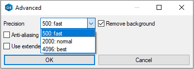
If you used the projection drawing method: Shading or Shading + Wire Frame, you can change the pixel resolution of the color shading by first selecting the projection and then selecting the context function: Properties > Advanced> Precision.
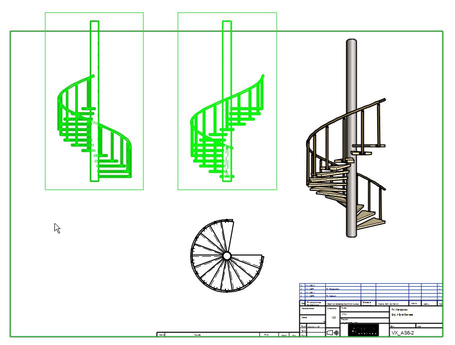
Cut the projections
Because the posts are unnecessarily long, you may want to cut them in the drawing.
-
Select projections.
-
Right-click function: Cut View.
-
Click to a position of the two (horizontal) lines. The geometry between the lines is removed from the drawing.
-
In the figures 1) and 2).
-
OK.
-
-
The program reverses the cut lines vertically, but since the projection is not cut horizontally, so
-
OK.
-
-
The program shortens both selected projections.
-
However, you can dimension the parts as if they were completely visible.
Save the drawing
-
File > Save or click


Save the model
-
File > Save or click
Download the finished assembly model (VX_AS6.vxz) with parts here