

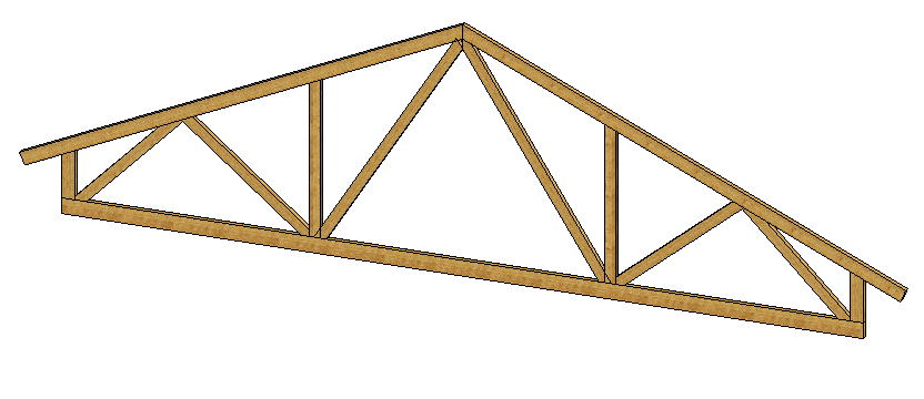
Exercise 6: Ceiling frame
This exercise was carried out with version 27.0 (Vertex 2021).
In this exercise you will learn to
-
To add profiles off-center.
-
To investigate the fabricability of the structure in case of collisions between the profiles.
-
Trim parts to other parts or faces.
Functions to be used:
-
New local part of the assembly.
-
Sketching: Two-point line, coincident constraint and dimensioning.
-
Sketching: Offset, Mirror.
-
Add > Profile.
-
Trim Profiles > Face.
-
Trim Profiles > Part.
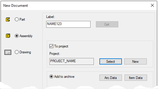
Create a new assembly
-
File > New > Assembly.
-
Enter the label (which is also the name of the model and by default will be the name of the drawing).
-
Enter the archive information by clicking Arc.Data.
-
Select the project where the model will be saved.
-
OK.
-
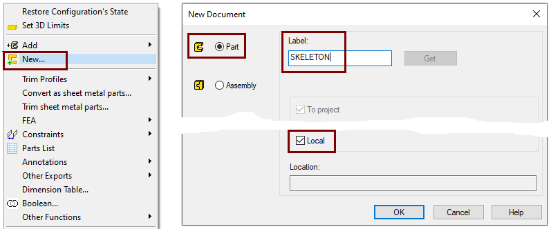
Create a new local part (Skeleton - Guide curve)
-
Right-click function: New > Part
-
Enter a name, eg SKELETON or JIG.
-
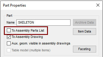
Define that the control curve part does not appear in the parts list
-
Right-click function: Properties
-
Deselect the settings: To Assembly Parts list, because this part is not desired in the parts list, after all it is a completely "intangible" part.
Sketch the skeleton (guide curve)
-
Right-click function: New Sketch > To vertical (XZ) plane.
-
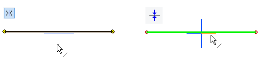
Start sketching by drawing a horizontal line.
-
Add a symmetry constraint to its endpoints with respect to the vertical line of the central cross.
-
Add a coincident constraint between the line and the horizontal cross of the centerline.
-
-
Sketch a vertical line in the middle.
-
Line style: Construction.
-
-
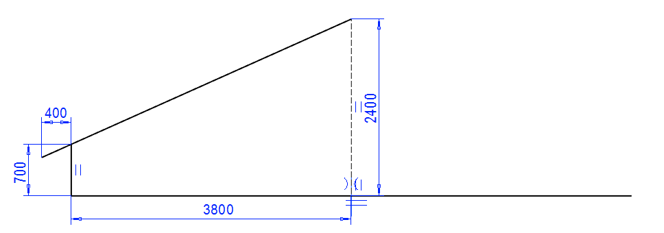
Sketch a vertical line at one end.
-
Line style: Shape.
-
-
Sketch a slash line that ends at the top of the construction line.
-
Add a coincident constraint between the diagonal line and the end of the short vertical line.
-
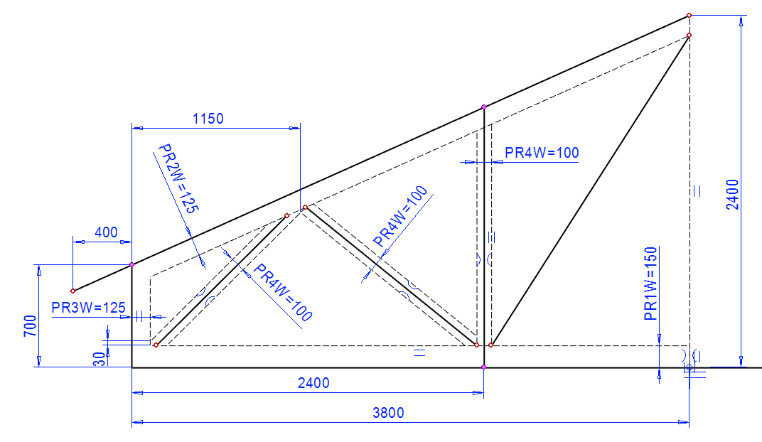
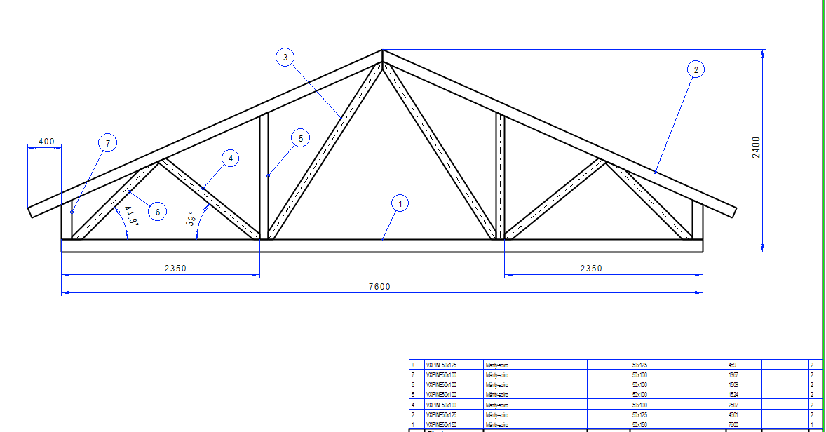
Add distance constraints, as shown in the figure.
Sketch the remaining lines on the other side of the cailing frame
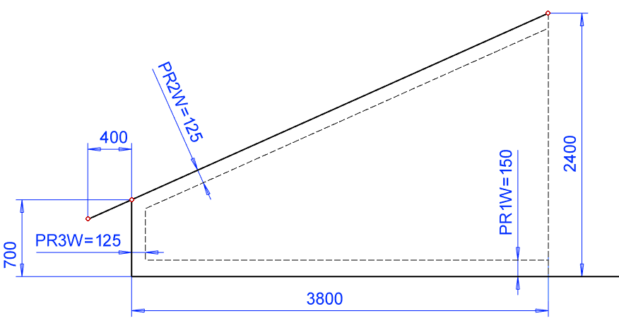
In order to get the diagonal supports to join each other as desired, you will need to draw construction line on the lines that describe the width of the profiles.
-
Sketch construction line that show the width of the profiles.
-
Add distance constraints. Fill also formula.
-
Add variables (formula) because if you need to resize profiles, the dimension table makes it easier to resize the sketch.
-
-
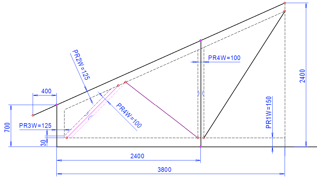
Sketch more lines.
-
Add the necessary symmetry and coincident constraints.
-
Dimension them.
-
Sketch the rest of the construction lines.
-
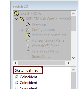
Add the rest of the symmetry and coincident and distance constraints so that the sketch is completely defined.
Mirror the lines on the left to the right
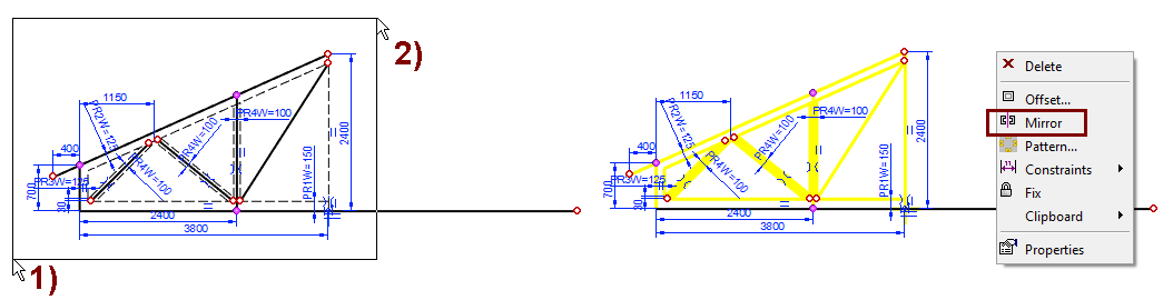
Select the geometry to be mirrored by fencing it
-
Click to a point outside the geometry on the left, in the figure 1).
-
Hold down the mouse select button and move the cursor to the right of the half geometry and release the button, in the figure 2).
-
Right-click function: Mirror.
-
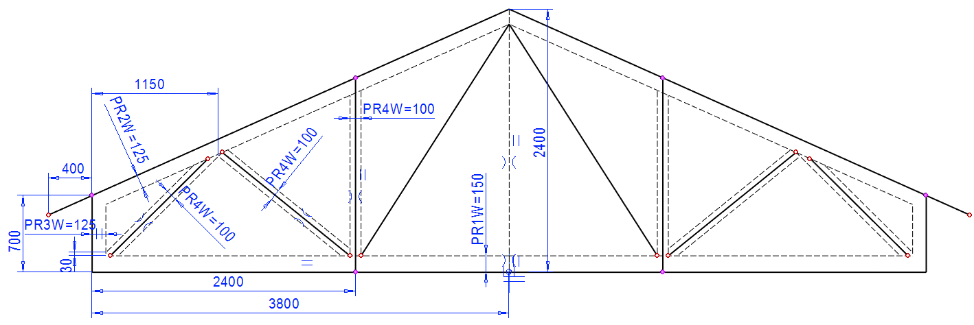
Point the mirror axis to the vertical construction line or the vertical line of the symmetry cross.
Operation:
-
Guide curve
Exit from part to assembly
-
OK.
Fencing direction:
-
When you fence the geometry from left to right, the lines that fall entirely within the area are selected.
-
When you fence the geometry from right to left, the lines that are partially or completely within the area are selected.
Exceptions:
-
Circles and arcs may be included or omitted by selection, depending on the location of their center.
Edit the selected set:
-
Press and hold Ctrl key and click the line you want to include in the selection set or the selected line you want to exclude from the selection set.
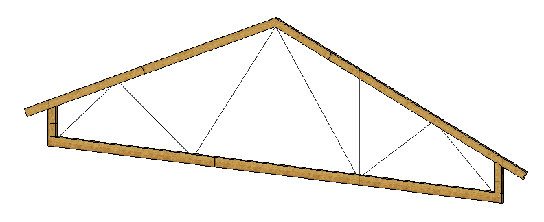
Add bottom and top profiles as well as vertical profiles for the ends.
-
Right-click function: Add > Profile.
-
The required profiles can be found in the library: Profile > Standard > Lumber > Timber.
-
Horizontal profile: 50*150.
-
Vertical and oblique profiles: 50*125.
-
-
Note that the cross section cannot now be placed on the guide curve from its default point (i.e. its center), because the sketch is made according to the external dimensions. Be careful when placing cross sections on the steering curve.
-
Use F8 or the

-
Use the right arrow or left arrow keys to rotate the profile cross section to the correct position.
-
Order of profile addition:
-
Add a horizontal profile (trimming method doesn't matter).
-
Attachment point in the middle of the (lower) short edge of the cross section.
-
Finish adding this size with OK to re-select the Timber and the new size.
-
-
Add oblique profiles:
-
Select the trimming mode: Trim automatically to edge.
-
Attachment point in the middle of the (upper) short edge of the cross section.
-
-
Add vertical profiles:
-
Select the trimming mode: Trim automatically to face.
-
Attachment point in the middle of the short edge of the cross section.
-
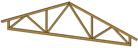
Add the rest of the profiles
-
Right-click function: Add > Profile.
-
The required profiles can be found in the library: Profile > Standard > Lumber > Timber.
-
Profiles size: 50*100.
-
Select the trimming mode: Trim automatically to face.
-
Attachment point in the middle of the cross section. (default).
-
-
Check the position of the cross-section before clicking the guide line and, if necessary, turn it with the arrow keys.
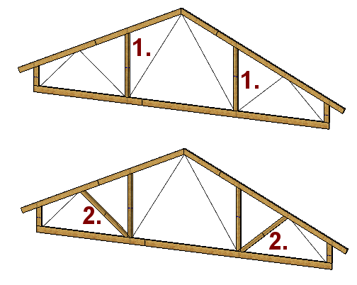
Order of profile addition:
-
Because the profiles overlap and are automatically trimmed to the faces in front of it, you should first add those profiles that should not be trimmed to other intermediate profiles. This makes trimming easier to later when you edit profile trims.
-
First add vertical profiles. In the figure 1.
-
Then add oblique profiles. In the figure 2.
-
The order in which other profiles are added does not matter.
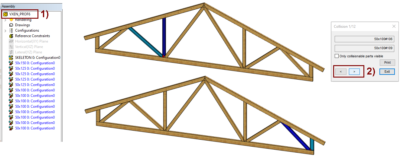
Find for profile collisions
All oblique profiles are now incompletely truncated, i.e. they go inside other profiles.
-
Click on the main symbol of the feature tree, in the figure 1).
-
Right-click function: Other function > Find Collisions.
-
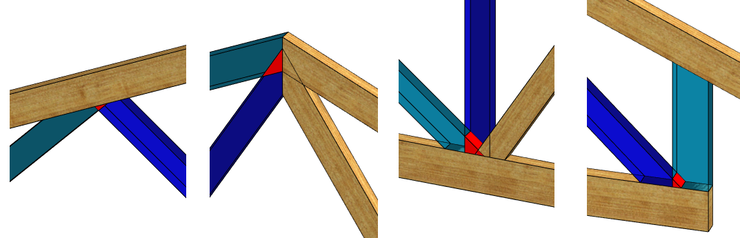
The program stains the parts involved in the collision with blue and the parts of the colliding space with red.
-
If there are many parts, select the option Only collisionable part visible, in which case the program will only displays two profiles at a time.
-
-
Use the < or > buttons in the dialog to find the next or previous collision, in the figure 2).
-
Use the Print button to get a list of colliding parts (the part ID and index number in the list).
You’ll also get tips on collisions when you click a profile and see if it extends inside another part.
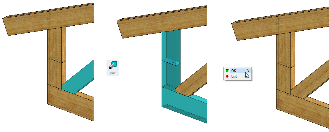
To eliminate collisions, trim the profile into parts.
-
Click the profile you want to trim.
-
Click the function from ribbon: Trim profiles to Parts.

-
Click on the parts.
-
Complete the trimming with the right-click function OK, or use the V key (it is a so-called "Done" acknowledgment).
This method allows you to trim all other profiles, but not the middle diagonal supports.
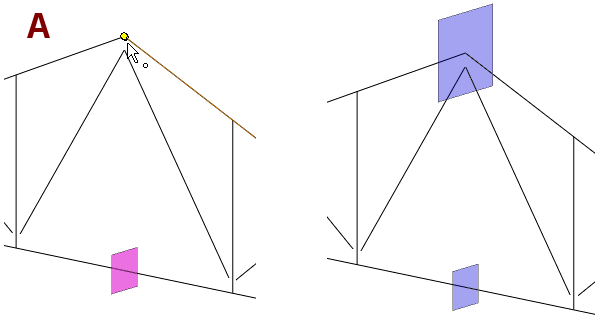
Prepare to trim the center diagonal profiles
Create an auxiliary plane in the SKELETON part that will be used to trim the diagonal profiles.
-
Click the part SKELETON.
-
Right-click function: Edit.
-
Hide other parts with the right-click function: Hide Others.
-
If the SKELETON part is not displayed, press G to return the auxiliary geometry.

-
-
Return the Lateral (YX) plane, if it is not already visible.
-
Select the auxiliary Plane and the top point, in the figure A.
-
Right-click function: New Plane.
Exit from part to assembly
-
OK.
-
If the profiles are hidden, use the right-click function: Restore Hidden.


-
That is, press and hold the Crtl and Shift keys and click the H key.
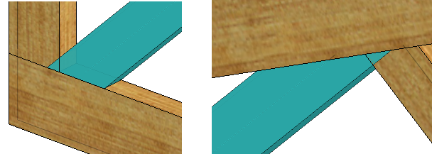
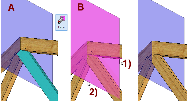
Trim middle oblique profiles to faces
-
Click the profile to be trimmed. In the figure A.
-
Click the function: Trim profiles to faces
-
Click on the target faces, in the figure B.
-
Click the bottom of the profile, in Figure 1).
-
Click the plane, in the figure 2).
-
Note that the Ceiling frame modeled on the basis of this exercise has not been evaluated in any way for its strength (load-bearing capacity).
Create a drawing for the model
For more detailed instructions, see the Modeling parts course exercise 5 Drawing of Model.
Save the model
-
File > Save or click


Download the Ceiling frame model (VX_PROF6.vxz) here.