

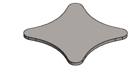
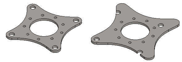
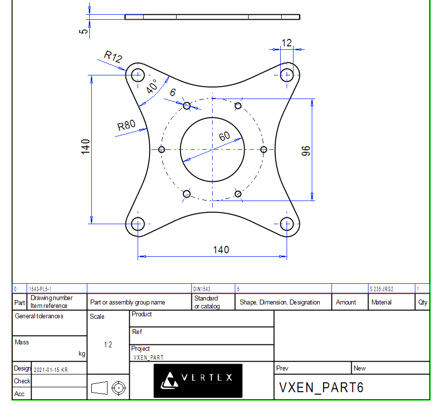
Exercise 6: Bracket
This exercise was carried out with version 27.0 (Vertex 2021).
In this exercise you will learn to
-
To mirror sketch geometry.
-
To create and edit patterns.
-
To bind the pattern to the geometry of the sketch.
Functions to be used:
-
We review sketching tools.
-
Pattern: Linear and Polar.
-
Edit pattern.
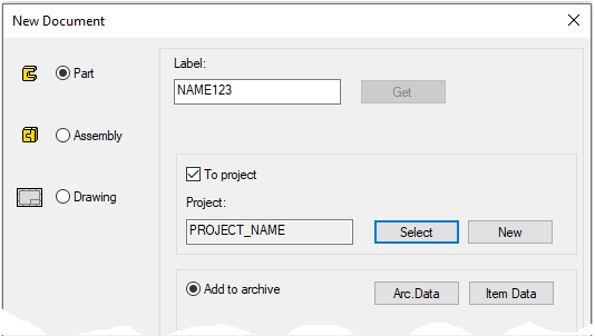
Create a new part
-
File > New > Part.
-
Enter the label (which is also the name of the model and by default will be the name of the drawing).
-
Enter the archive information by clicking Arc.Data.
-
Select the project for the model.
-
OK.
-
Create the first feature
-
New Sketch > To horizontal (XY) plane
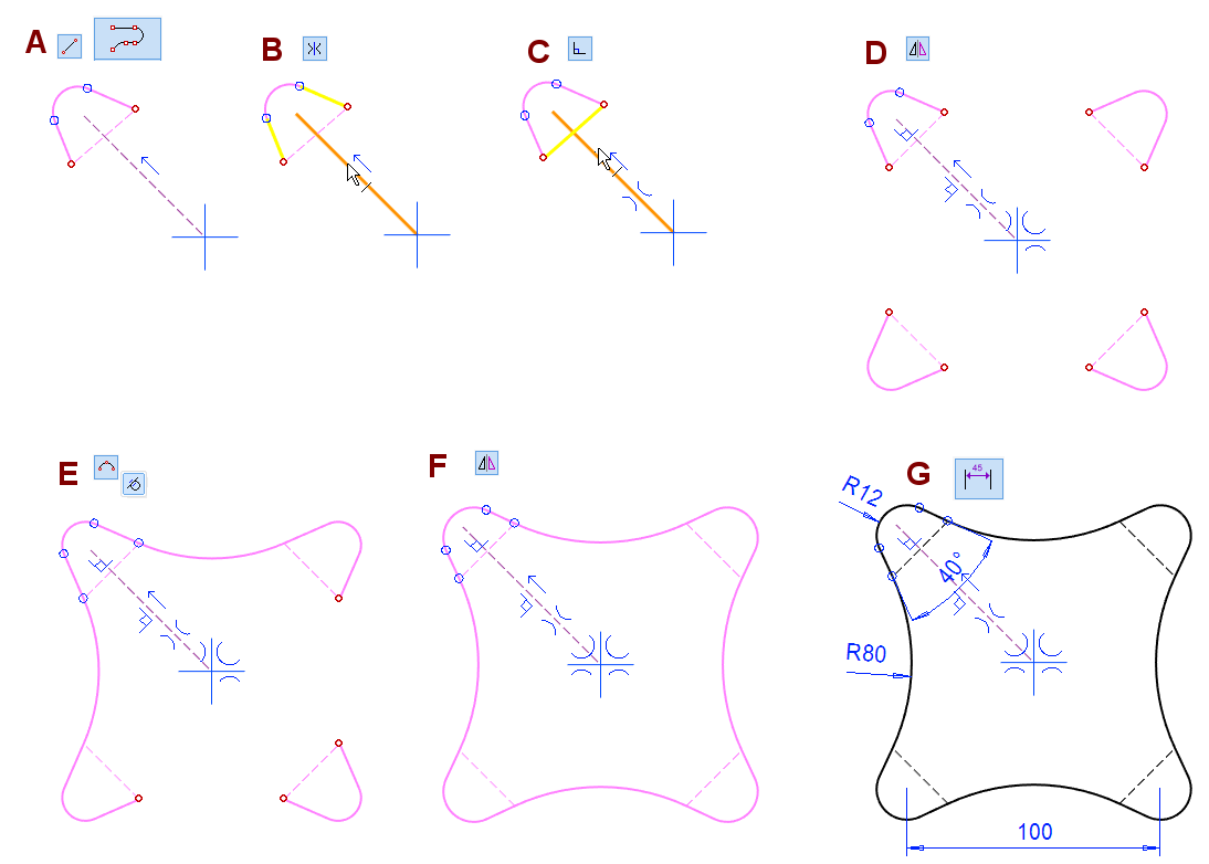
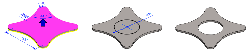
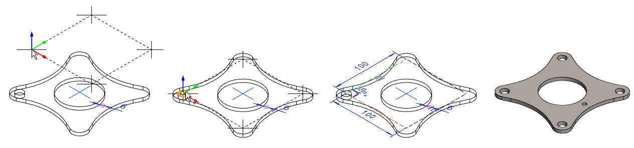
Sketch the shape
-
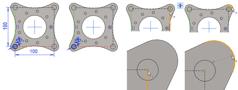
Start by sketching the construction line in the locked (135 degrees) direction. The figure A.
-
Sketch a smart line around the end of the line. The figure A.
-
Add a symmetry constraint to the "lug" lines. The figure B.
-
Add a perpendicular constraint between the construction lines. The figure C.
-
Mirror the lugs with respect to the lines of the central cross. The figure D.
-
two different mirrors.
-
-
Sketch a tangential arcs. The figure E.
-
Mirror or sketch the tangential arcs. The figure F.
-
Dimension the sketch. The figure G.
-
Select

Operation
-
Boss and Extrude.
-
Length: 5.
Model a hole in the center of the part
-
Click the face.
-
Right-click function: New Sketch > Face.
Sketch the shape
-
The function: Circle. (Circle with Center and Radii Point).
-
Add a Diameter constraint: 60.
-
Operation:
-
Cutout - Extrude - Thru all.
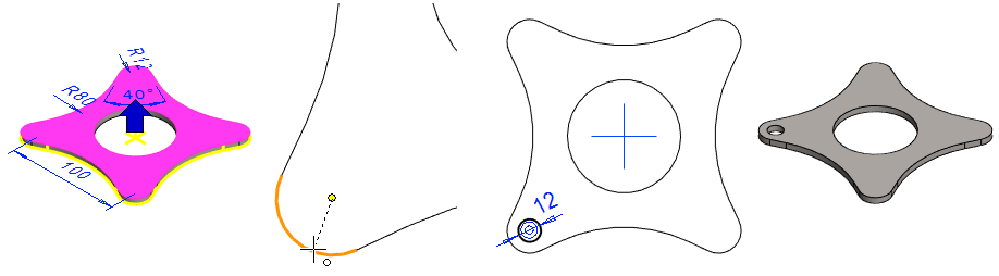
Model the hole in the lug
-
Click the face.
-
Right-click function: New Sketch > Face.
Sketch the shape
-
The function: Circle. (Circle with Center and Radii Point).
-
Sketch a circle so that the center coincides with the center of the lug.
-
-
Add a Diameter constraint: 12.
-
Operation:
-
Cutout - Extrude - Thru all.
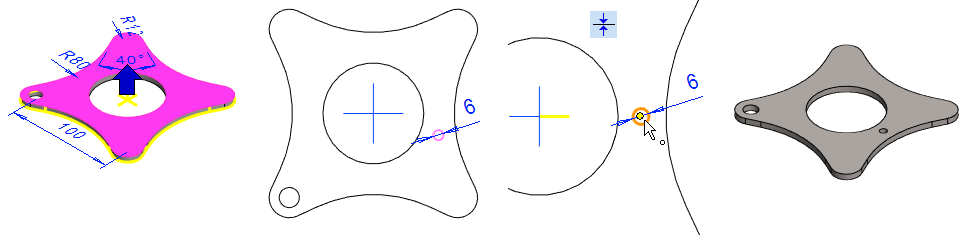
Model a hole
-
Click the face.
-
Right-click function: New Sketch > Face
Sketch the shape
-
The function: Circle. (Circle with Center and Radii Point).
-
Add a Diameter constraint: 6.
-
Do not increase the distance of the circle from the center cross yet.
-
Add a coincident constraint between the center of the circle and the horizontal line of the center cross. This constraint may be omitted. The hole can be positioned later when making a pattern.
-
Operation:
-
Cutout - Extrude - Thru all.
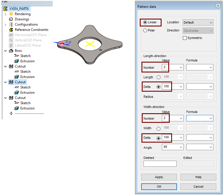
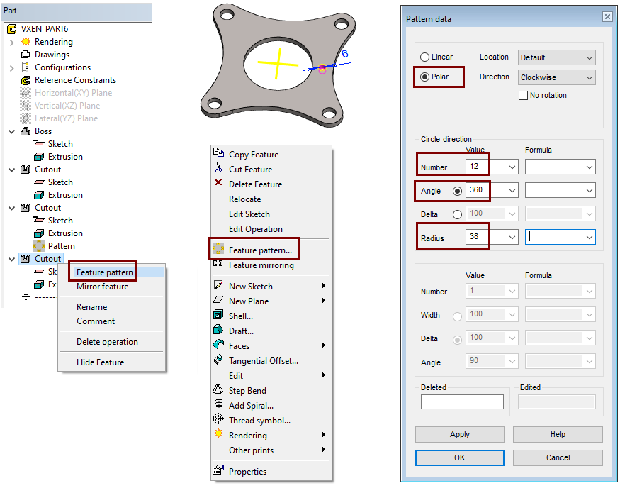
Create a pattern from hole of the lug
-
To select a feature, either click it in the feature tree or select a face of feature from the model.
-
Right-click function: Feature pattern.
The program opens a dialog
-
Accept the default: Linear.
-
Accept the default Location: Default. (= on the same face as where the sketch of the feature is located.)
-
Enter values in the Lenght-direction:
-
Number: 2 (Quantity)
-
Delta: 100.
-
-
Enter values in the Width-direction:
-
Number: 2 (Quantity)
-
Delta: 100.
-
-
OK.
Position the auxiliary geometry so that the position of the cursor is in reasonable proportion to the feature.
-
Here: A corner is attached to the center of the circle.
-
In reality, only the direction of the auxiliary geometry matters.
-
The members of the pattern come in relation to the feature as in the auxiliary geometry the crosses are drawn
After the placement of the auxiliary geometry, the program presents a sketch where it is possible to change the dimensions.
-
OK completes the pattern.
Create a polar pattern from a small hole
-
To select a feature, either click it in the feature tree or select a face of feature from the model.
-
Right-click function: Feature pattern.
The program opens a dialog
-
Change the pattern type: Polar.
-
Accept the default Location: Default. (= on the same face as where the sketch of the feature is located.)
-
Enter values in the Circle-direction:
-
Number: 2 (Quantity)
-
Angle: 360. (Default value = the members of the pattern come evenly on the circle).
-
Radius: 38.
-
-
OK.
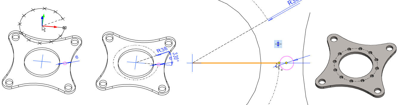
Position the auxiliary geometry so that the cursor hits the center of the polar feature.
-
Add a coincident constraint between the center of the hole and the endpoints of the auxiliary geometry line.
-
If necessary, you can change the radius dimension.
-
OK: complete the pattern.
Save the model
-
File > Save or click


Change the values of polar pattern.
-
Select: Pattern (From the last stage of history).
-
Right-click function: Edit pattern.
-
Change the values:
-
Number: 12 > 9.
-
Radius: 38 > 41.
-
-
OK.
If the main dimensions of the part are modified so that the hole spacing of the first sketch increases from 100 mm to 120, then the holes in the lugs will be in the wrong place.
-
Of course, this can be corrected by modifying the pattern of holes in the lugs after changing the dimensions of the first sketch.
The problem can be prevented in advance if the auxiliary geometry of the pattern is binded to the geometry of the part.
Bind a pattern of holes in the geometry
-
Select: Pattern (From the second to last stage of history).
-
Right-click function: Edit pattern.
-
The Pattern data dialog appears.
-
-
Remove the dialog Pattern data with OK.
-
Remove the length and the width dimensions.
-
Add a coincident constraint between the end point of the auxiliary geometry line and the center of the lug.
Alternatively, in this model, two symmetry constraint could have been added between the auxiliary geometry lines and the center cross lines.
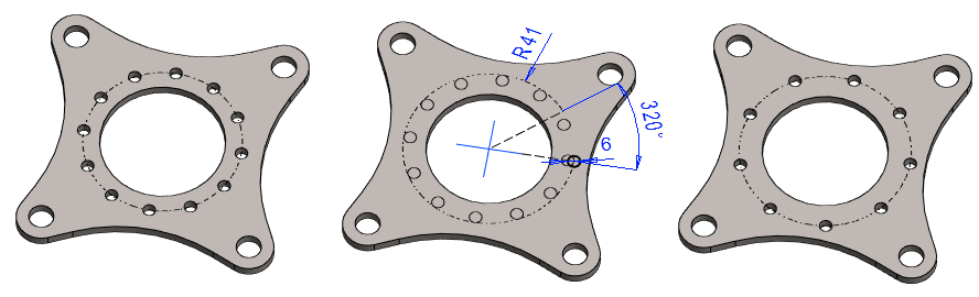
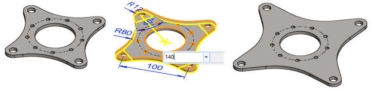
Change the dimensions of the bracket
-
Select the first feature from the history tree.
-
Select dimension 100.
-
Move the cursor slightly to the top right.
-
Click on the Mini Toolbar.
-
Enter the new dimension 140.
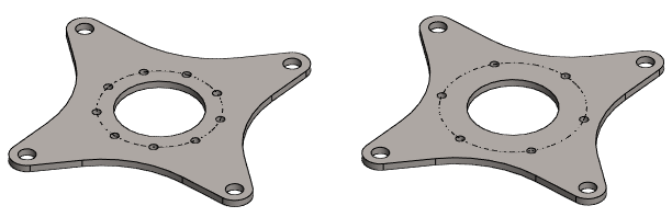
Change the values of polar pattern.
-
Select: Pattern (From the last stage of history).
-
Right-click function: Edit pattern.
-
Change the values:
-
Number: 9 > 6.
-
Radius: 41 > 48
-
-
OK.
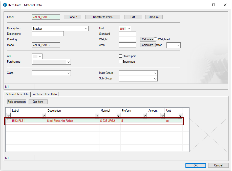
Get material data information from the item database
-
Right-click function: Item Data.
-
At the bottom of the dialog: Get Item, in the figure 1).
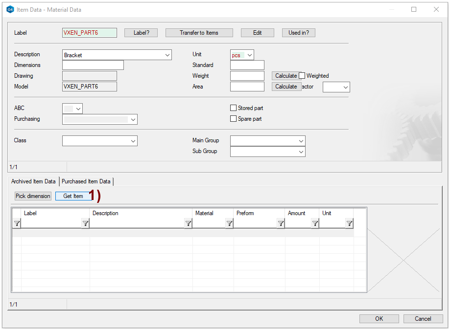
-
The Class selection menu is opened.
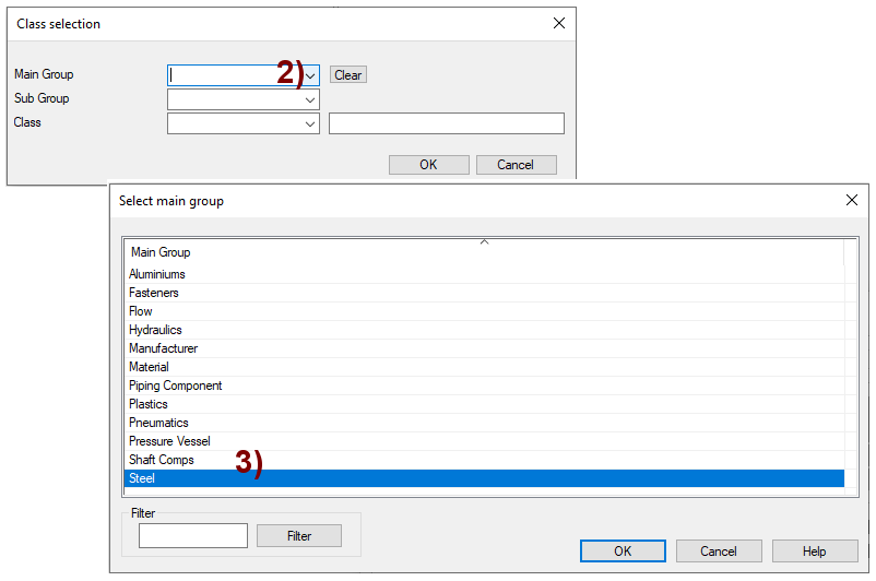
-
Press the preselection button in field Main Group, in the figure 2).
-
The Select main group menu us opened.
-
Select the correct group, in the figure 3).
-
Here: Steel.
-
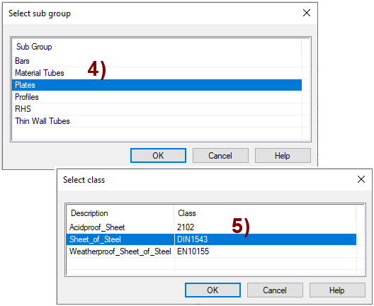
-
The Select sub group menu is opened.
-
Select the correct sub group, in the figure 4).
-
Here: Plates.
-
-
The Select class menu is opened.
-
Select the correct class of item, in the figure 5).
-
Here: Sheet_of_Steel.
-
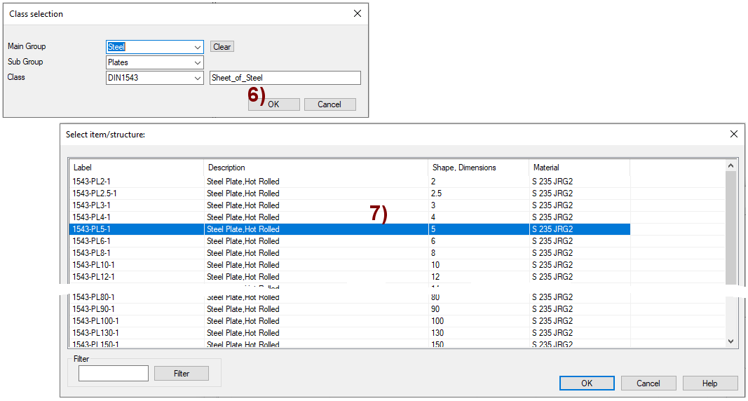
The search criteria for menu Class selection have been added
-
OK perform a search, in the figure 6).
-
The program opens a list of items that meet the search criteria.
-
Select a row, in the figure 8).
-
OK: copy the data to the part.
Material data information is displayed under the Item
Create a drawing for the model
See Exercise 5 for more detailed instructions.
Save the drawing
-
File > Save or click
Save the model
-
File > Save or click