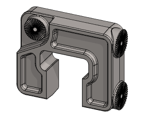
Exercise 2: Drawing of Sonar Body
This exercise was carried out with version 27.0 (Vertex 2021).
In this exercise you will learn to
-
Adding Bill of Material (raw material) for a part.
-
Create a drawing for the model.
-
Defining drawing properties
-
Dragging and positioning the projections in the drawing.
-
Adding new projections to the drawing.
-
Increase in sectional and partial sections projections.
-
Adding sectional and partial sections projections.
-
Changing scale of the drawing.
-
Changing scale of an one (isometric) projection.
-
Editing drawing archive data.
-
Open the model through the drawing
Functions to be used:
-
Item Data and Material.
-
New Drawing.
-
Projection (Adding new projection).
-
Cut view .
-
Detailed View.
-
Properties (of Drawing and of Projection).
-
Archives > Data.
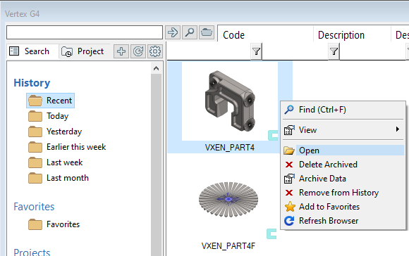
Open the model made in the previous exercise
-
File > Open.
-
or press B key and browse the archive. You can also search for a model under the History section of your browser.
-
-
Select the model.
-
Right-click function: Open.
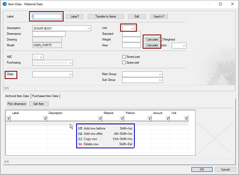
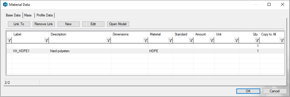
Adding Bill of Material (raw material) to the part.
The item data can be written manyally or it can be retrieved from the item database (d_COMPONENTS). In this exercise, the item data is written manually.
-
Right-click function: Item Data.
-
Complete the item data to the section at the top of the dialog. (The program copies first this data from model archive, but any changes you make remain).
-
At the bottom of the dialog, add the raw material information for the part. This data is then written in the parts list of the drawing.
-
Click the first line.
-
Right-click function: Add row before.
-
With the material field preselection button you can search materials that are saved to the material database d_SPEC1. (You can edit this database by function System > Application > Material).
-
If you only want to have part list information in the drawing, and you do not need item information of your model, for example for an ERP system, you can also use the Material function 
-
You can edit the material database d_SPEC1 by System > Application > Material.
The Vertex G4 contains various databases.
All Item Data of raw materials and components used by the company, can be stored to the item database, d_COMPONENTS.
If the product data management system is in use (Vertex Flow), the items are managed in Flow.
You can edit the item database:
-
System > Application > Item Database: Browse and Edit.
-
Add a line with a right-click function
-
Delete a line with a right-click function
-
-
You can edit the contents of the database with Excel by a right-click function: Export > Modify in Excel now and import back.
-
From the item data card , you can store your model item data with its structure to the item database with the function: Transer to items > OK.
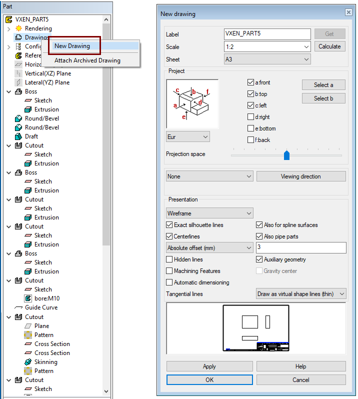
Create a drawing
-
In the feature tree, click Drawings.
-
Right-click function: New Drawing.
In the dialog New drawing, select data:
-
Scale: 1:2
-
Sheet: A3
-
Select projections: front, top and left.
-
Tangential lines: Draw as virtual shape lines (thin).
-
Select OK and you can fill in the archive data.
Label: Accept or change the drawing label (= Drawing number).
Scale: Select the scale according to the drawing standard
-
You can also change the scale of the drawing later from the drawing properties.
-
You can also enter other scales, but they are usually only used for isometric or perspective projections.
Sheet: Select a sheet from the list (you can also select the sheet later).
Project (Direction of projections): Select directions.
-
You can see the directions indicated by the program in the Tool Strip.

-
You can also point to the front projection with the Select a.
-
If you use this Select a button, the program adds a Select b button. This allows you to click a plane in the model that determines the top direction.
-
At the bottom of the dialog, you can see how the projections will fit on the selected sheet at the selected scale.
Projection space: Use the slider to adjust the space between projections.
A list of isometric projections opens at the back of the None button if you want to add one immediately to the drawing.
Viewing direction: You can enter a mathematical direction or press the Select at Model and then click to a plane in the model whose projection is added to the drawing.
-
If you do not click to any face in the model, but acknowledge the plane assignment with a "Done" key (= middle mouse button or V key) a projection is added in the direction in which the model is at that moment.
Presentation:
-
Wireframe: Draw only lines from the part (Hidden lines missing).
-
Shading: The part is drawn shaded, without lines, so you can't dimension the drawing.
-
Shading+Wireframe: The part is drawn shaded and has lines.
-
LightWorks-shading: The part is drawn as Photorealistic (slows down the generation of the projection).
-
LightWorks-shading+Wireframe: The part is drawn as Photorealistic and has lines included.
Exact silhouette lines, Also for spline surfases: These can be used to influence the drawing of diverse roundings in a drawing.
Centerlines, Alaso pipe parts: The program draws the center crosses of the holes as well as the axes of symmetry of the rotationally symmetrical parts.
Absolute offset (mm): Exceeding the length of the centerlines in relation to the geometry.
Hidden lines: Hidden lines are drawn as dashed lines.
Auxiliary geometry: Control curves and cross sections are drawn.
Machining Features: If the model has a so-called tool geometry, then it is drawn on it.
Gravity center: If the weight is calculated in the model, then the center of gravity mark is added to the projection.
Automatic dimensioning: Allows you to automatically add dimensions based on settings.
-
Settings button appears, if you select Automatic dimensioning.
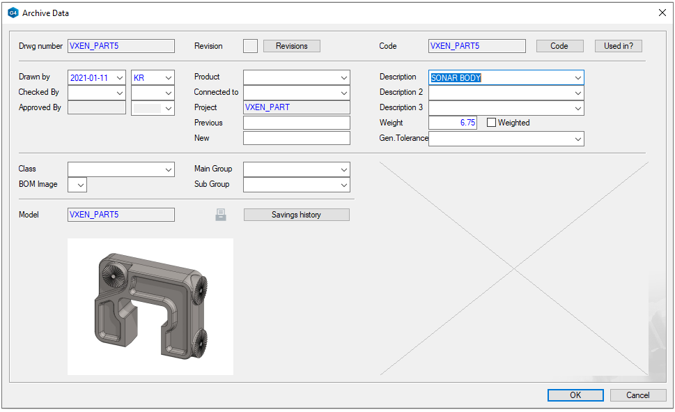
Review and accept the archive information
-
The program writes archive data to the drawing.
-
Edit the archive data to fit the drawing.
-
OK: accept the archive data and create the drawing.
The importance of the Archive Data
-
Some of this information appears in the Title bar of the drawing.
-
You can utilize this data as a search criterion when you search for drawings by choosing File > Open > Drawing.
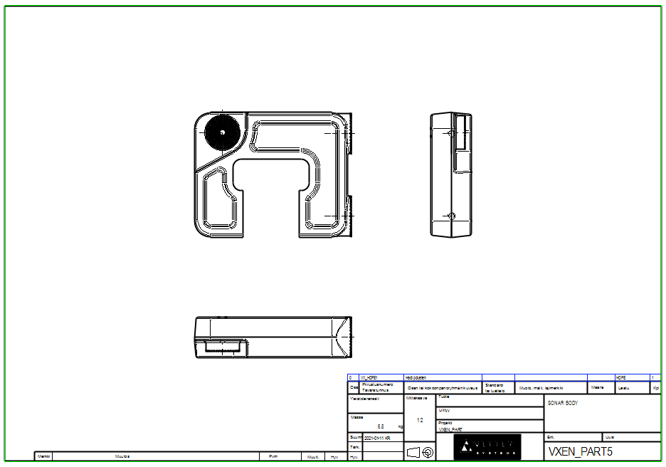
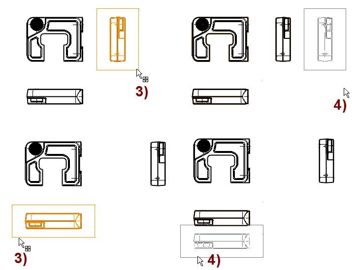
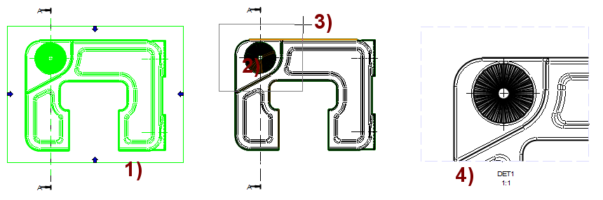
Drag projections
When you select a Front projection and drag it, other related projections are dragged along.
-
Move the cursor close to the edges of the projection, giving the projection a focus color, in the figure 1).
-
Press and hold the mouse select button. At the same time, drag the projection, in the figure 2).
-
Release the button to drop the projections in the new location.
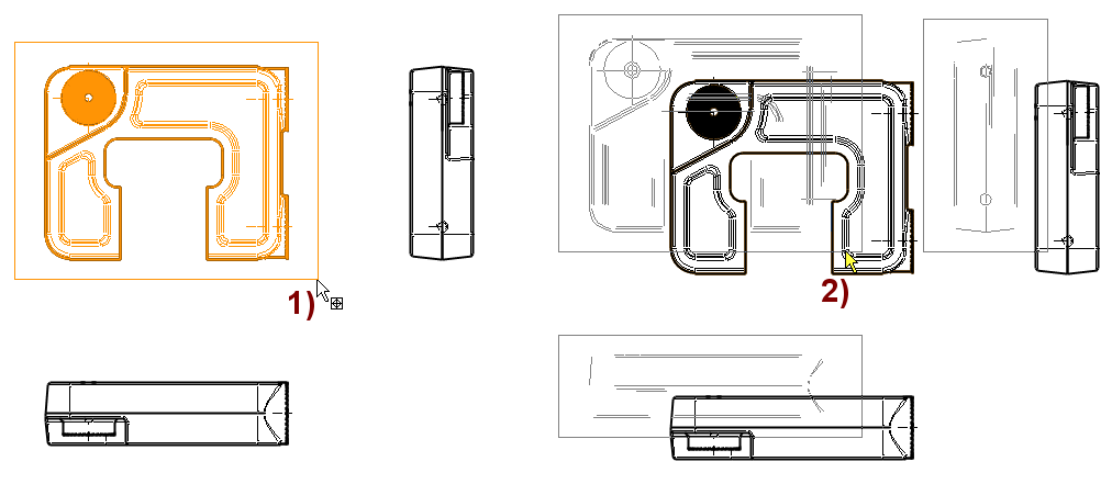
When you select an other projection and drag it, they slide relative to the Front projection.
-
Try dragging left and top projections, in the figure 3) and 4).
-
They do not drag other projections with them.
-
If the projections are in the "wrong place" in the drawing, then instead of dragging the projections, you can also drag the sheet.
-
After dragging the sheet, press F5 to recalculate the drawing boundaries.
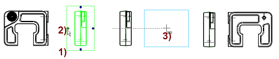
Add projection: Back
-
Click to the projection: From the left, in the figure 1).
-
Four blue arrows appear around the projection to describe viewing directions.
-
-
Click the left arrow, shown in the figure 2).
-
The program "throws" the projection to the side according to the projection rules, in the figure 3).
-
If necessary, drag the projection and click it into right place.
The projection created as described above follows the projection by which the projection was created.
-
It also drags in relation to this projection.
If you create a new projection with the Projection function of Ribbon or (when none projection is selected) with the Right-click function: Projection, then this projection is not relative to the previous projections, and it can be dragged freely to the new location.
-
If you make a new projection of such a projection with the blue arrows described above, then it is also detached from the "mother" and can be dragged freely to a new location.
-
If you make a new projection by first selecting the projection and then the right-click function: Projection, then the new projection is connected to the "mother" projection.
You can add coincident and distance constraints for positioning projections relative to each other.
-
Using constraints is the only option that allows you to tie, for example, a section view to the same level as a "parent" projection.
-
Note that the projection is bound to another projection with constraints not drag with the "mother." Only when the constraints are resolved, e.g. with the F5 key, do the projections settle into the positions according to the constraints.
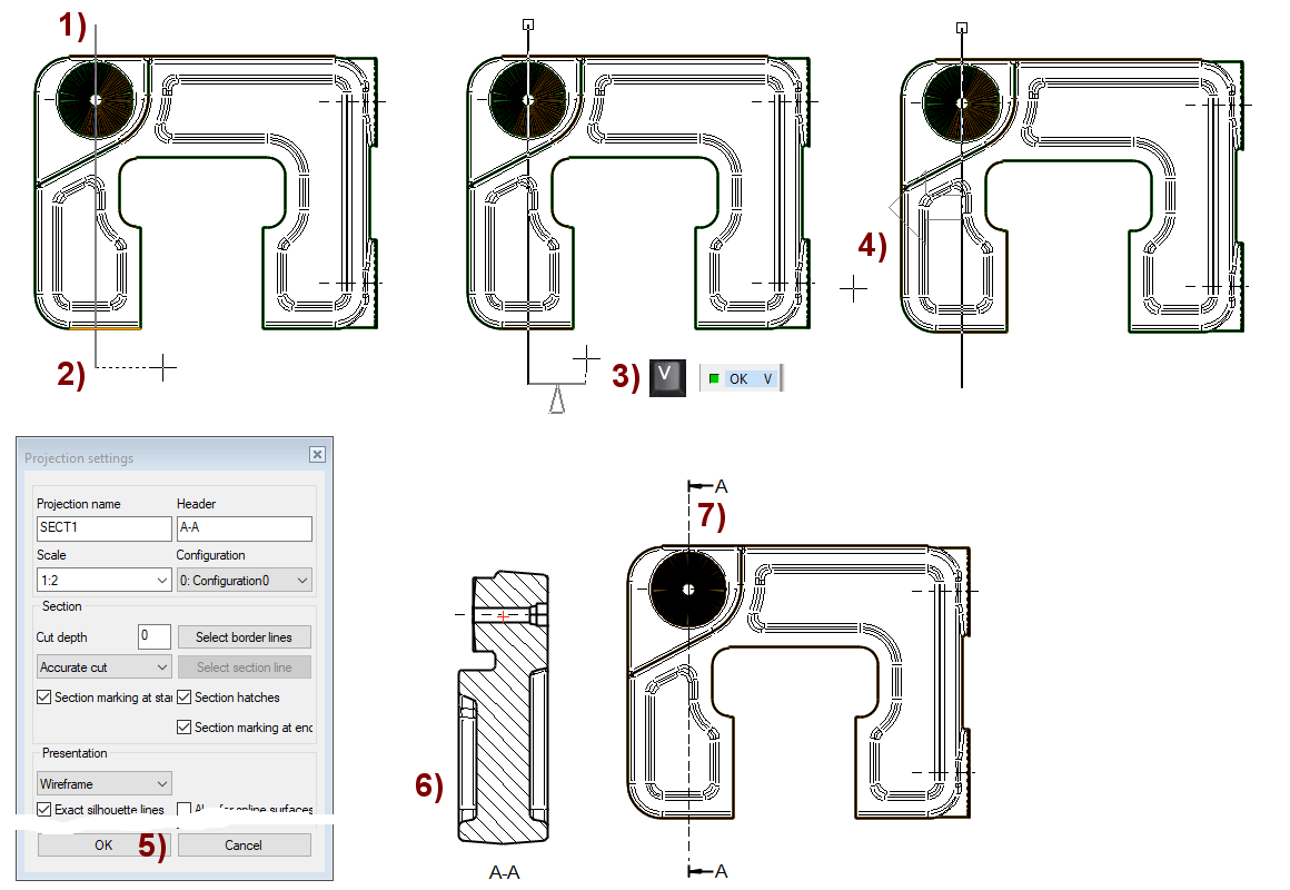
Create Section view
-
Click projection.
-
Select the section line with two dots (or click a pre-drawn section line), in the figures 1) and 2).
-
OK or "Done" key (= middle mouse button or V key), in the figure 3).
-
Select the viewing direction. You can change the direction of the arrow to move the cursor, in the figure 4).
-
Define the properties of the projection, in the figure 5).
-
Select the location of the section view, in the figure 6).
-
The program adds a cut line to the "parent" projection, in the figure 7).
If the part is dimensionally variable and the section should always remain at a certain point in the geometry (e.g. in the middle of the hole), then before making the section view it is advisable to draw either a segment line or a polyline and tie it to the geometry with constraints.
-
In this case, the section view follows the geometry, even if the model is varied after the section is made.
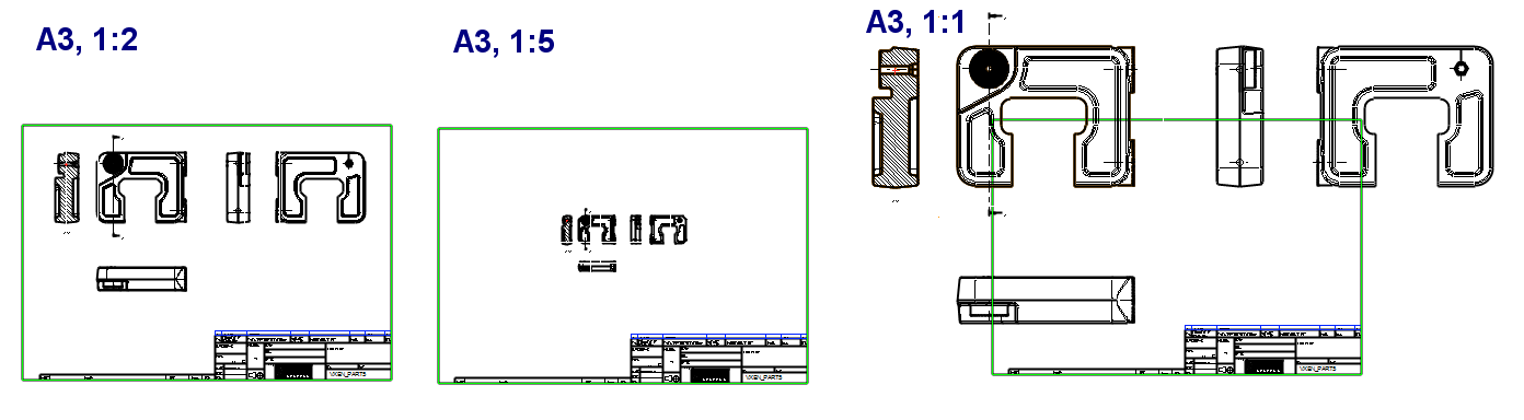
Change the scale of drawing
If the projections do not fit on the sheet, it is possible to either change the sheet to a larger one or change the scale of the drawing.
-
Right-click function: Properties (when nothing is selected) the Drawing Settings dialog is opened.
-
Scale: Try the 1:5 and 1:1 scales, return to the 1:2 scale.
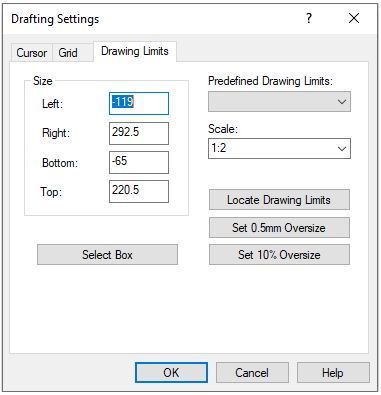
The sheet automatically scales to fit, so you do not need to change it if you change the drawing scale.
The texts and dimensions that come to the drawing are always proportional to the scale, so the height of the text is always 3.5 mm, even if the scale in the drawing changes.
But the position of the dimensions and the texts remains in the places assigned to them, so the dimensions can interleave if you made first dimensioning the drawing and then resize it to a smaller scale (e.g. 1:1 => 1:2.5).
-
For this reason, it is recommended that you search for a suitable sheet before dimensioning and adjust the geometry by scaling the drawing.
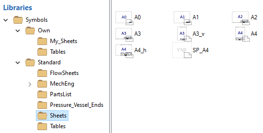
You can change the drawing sheet
-
Delete the existing sheet, select it:
-
Right-click function: Delete or press the Delete key.
-
Right-click function: Read Symbol (or Symbols > Read Symbol on the Ribbon.)
-
Libraries > Symbols > Standard > Sheet or Libraries > Symbols > Own > My_Sheet.
-
-
Select a symbol (e.g. by double-clicking).
-
Select a location and click it into right place.
Create Detailed View
-
Click the projection, in the figure 1).
-
Right-click function: Detailed View.
-
Select to the center of the detailed view, shown in the figure 2).
-
Select the corner point of the detailed view, shown in the figure 3).
-
Define the properties of the detailed view.
-
Scale: 1:1 (Because the drawing was made on a scale of 1:2)
-
Header: DET1 (or something else if you want).
-
-
Select the location of the detailed view, in the figure 4).
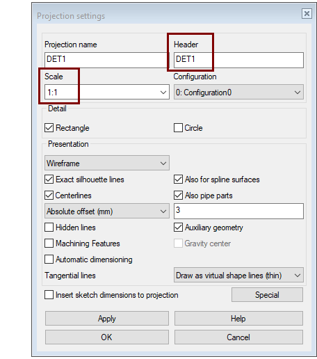
The Detailed View projection can be rectangular or elliptical (round).
-
The ellipse projection is always drawn by a wireframe representation.
-
A rectangular projection can also be a shaded projection.
Other properties
-
These are described in the New Drawing Dialog box earlier in this exercise.
-
The Special button opens a dialog that allows you to bind the detailed view, so that projection follow the measurement points added to the model separately.
Add detailed view only after you have decided "to lock" scale of the drawing.
If you change the scale of drawing after adding a detailed view, the geometry of the detailed view change in the same proportion.
-
In this case, the scale of the detailed view's header, provides incorrect information.
-
This incorrect information will be corrected as long as you visit the Properties of the detailed view and exit with OK.
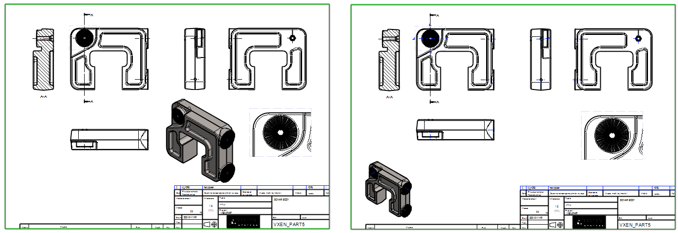
Create isometric and shaded projection
-
Right-click function: Projection (or Ribbon function Projection).
-
Select the direction of the projection: ISO, -45 Front Right.
-
Select the Presentation: Shading+Wireframe.
-
Other options in the New Projection dialog may be defaults.
-
Select the location of the Projection.
Select the projection and the right-click function: Properties.
-
Choose a smaller scale, e.g. 1:2.5
-
You can also enter a free scale, such as 1:3
-
Drag the projection to the appropriate location.
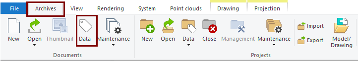
You can change the archive information of a drawing at any time
-
Activate the drawing window.
-
You can change the activity of the drawing and model window, eg Tab-Ctrl.
-
-
The function: Data (on the Archives tab of the ribbon, shown in the figure.
-
Click OK to exit editing the archive data.
-
Use F5 to refresh the drawing to update the title bar information.
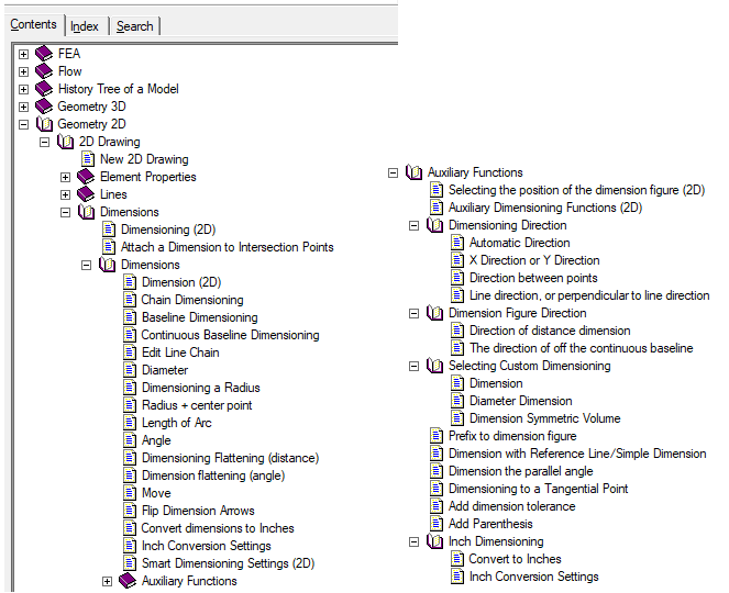
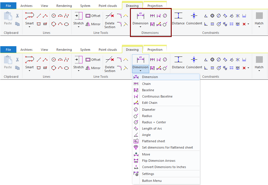
Dimension the drawing
-
Use the functions in the Dimensions group.
-
The Dimension function is suitable for the following cases:
-
The length of the line segment or segment of polyline.
-
The radius of the arc.
-
The diameter of the circle
-
The distance or angle of the two line segments, depending on whether the lines are parallel or not.
-
Check out the dimensioning instructions using F1 or 
-
Contents > Geometry 2D > 2D Drawing > Dimensions.
Save the drawing
-
File > Save or click


If you forgot to save the model after creating the drawing, then the model and drawing can be found through the archive, but the Drawings section of the model feature tree does not recognize the drawing.
You can fix this by attaching an archived drawing to the model:
-
In the feature tree, click Drawings.
-
Right-click function: Attach Archived Drawing.
-
Search the drawing in the archive, e.g, under the History > Recent folder.
-
Double-click the drawing to select it.
Save the model
-
File > Save or click
Note that the model must be saved at least once after the drawing is created so that drawing information is stored to the model's feature tree.
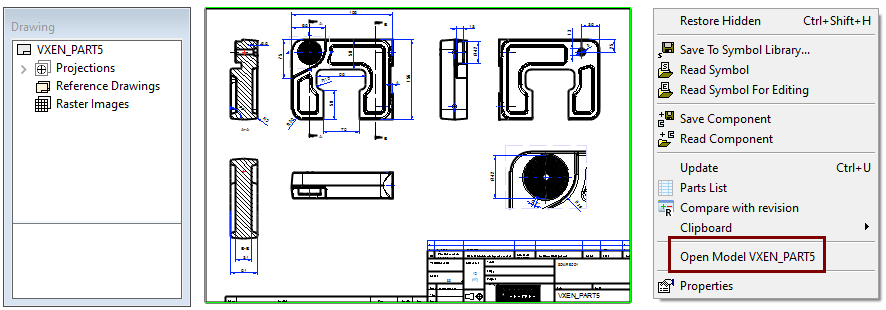
You can also open the model through the drawing
Unlike, for example, Solidworks drawing, Vertex drawing knows from which model it is made of.
If you have opened the drawing and notice the model needs to be changed, open the model:
-
Right-click function: Open Model XXXX (Where XXX is the model name)
If the drawing has projections from more than one model, you can open the model that connects to the projection:
-
Click the projection
-
Right-click function: Open Model XXXX (Where XXX is the model name)