

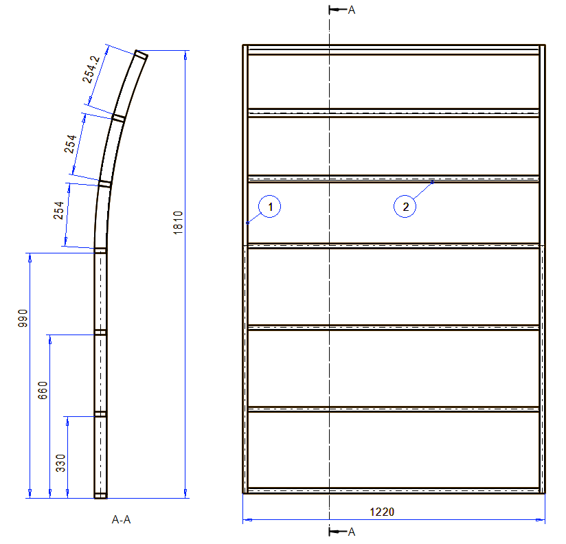
Exercise 5: Curved wall
This exercise was carried out with version 27.0 (Vertex 2021).
In this exercise you will learn to
-
To orientation the cross section of the profile.
Functions to be used:
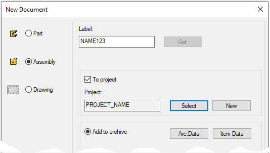
Create a new assembly
-
File > New > Assembly.
-
Enter the label (which is also the name of the model and by default will be the name of the drawing).
-
Enter the archive information by clicking Arc.Data.
-
Select the project where the model will be saved.
-
OK.
-
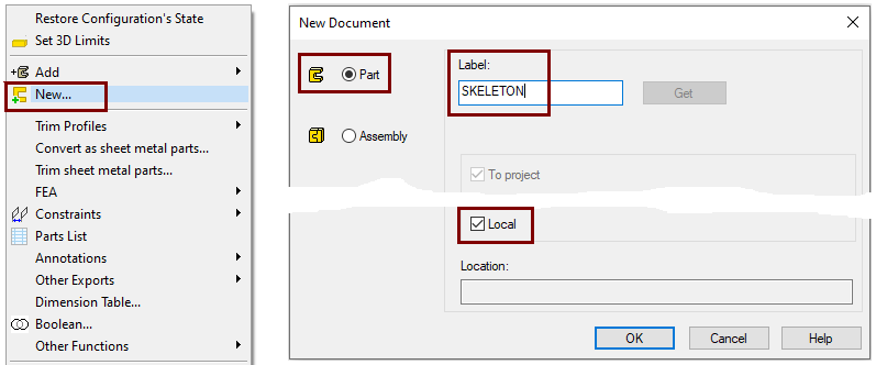
Create a new local part (Skeleton - Guide curve)
-
Right-click function: New > Part
-
Enter a name, eg SKELETON or JIG.
-
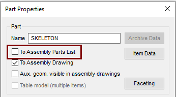
Define that the control curve part does not appear in the parts list
-
Right-click function: Properties
-
Deselect the settings: To Assembly Parts list, because this part is not desired in the parts list, after all it is a completely "intangible" part.
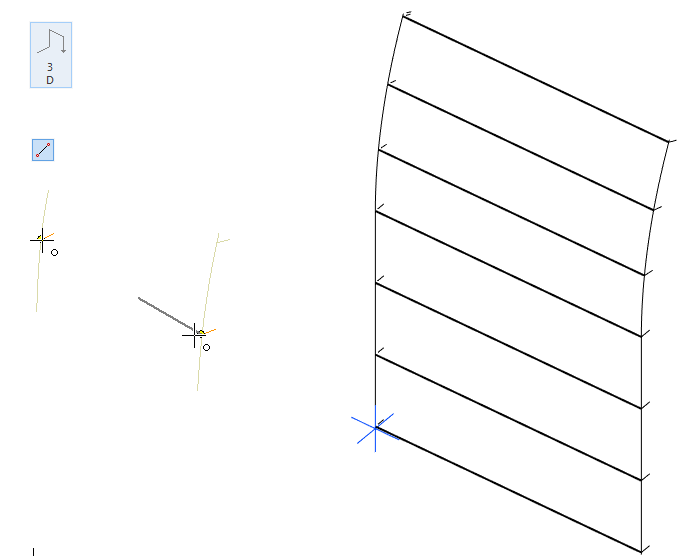
Sketch the skeleton (guide curve)
-
Right-click function: New Sketch > To lateral (YZ) plane.
-
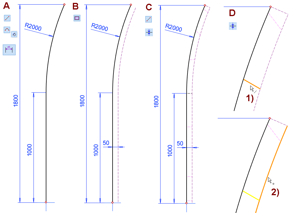
Sketch the shape, Two-point line + Arc with Three Points, in the figure A.
-
Add a parallel line: Offset: 50, in the figure B.
-
Change the properties of the parallel lines to a Construction line, as they do not need to appear in the model.
-
Sketch 8 two-point lines, use the line style Guide line, in the figure C.
-
Start with the shape line and end the line on the construction line.
-
Align the bottom four lines horizontally.
-
The next three lines in an oblique position (approximately towards the center of the arc)
-
Top line of control curves from end to end.
-
-
Define the top four lines perpendicular to the tangent of the arc as follows. In the figure D.
-
Coincident constraint.
-
Click to the line, in the figure 1).
-
Click the center of the arc from inside the arc, in the figure 2).
-
If the two-point line seems to disappear, press F5 to calculate the work area limits and you see an "escaped" line. The escape is due to the fact that the direction of the line together with the Coincident constraint reposition the line.
-
If necessary, drag the line near the right places.
-
If necessary, add Coincident constraint between the endpoints of two-point lines and the construction line.
-
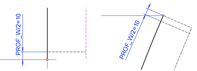
Add two distance constraints (half the thickness of the profile, e.g. 10).
-
For the lowest line, the distance from the centerline of the center cross.
-
Between the top line and the end point of the next line.
-
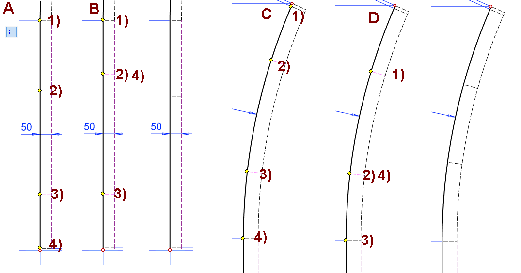
Position the lines using the Equal Distance constraint, so that they divide the vertical segment into three equal parts and the arc into three equal parts. To do this, the Equal Distance constraint must be used four times.
-
Function: Equal Distance.
-
Four different points are clicked in the figures A and C.
-
You can stop adding the constraints and try dragging another line so you can see that both lines are moving.
-
-
In the figures B and D, the middle point is clicked into the second and fourth points.
Operation
-
Guode Curve.
Greate another guide curve of the same shape.
-
Return the Lateral (YZ) Plane from the feature tree (if it is not already visible).
-
Click on the above Plane.
-
Right-click function: New Sketch > Parallel.
-
Enter 1200 for the value and LEN for the formula.
-
-
Right-click function: Line > Copy to Sketch Plane or with the Copy Lines function on the ribbon.
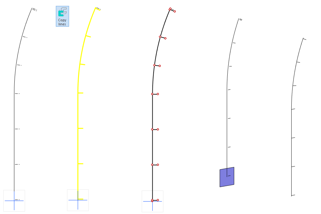
Create control curves for horizontal profiles
-
Use the 3D ribbon function to enter 3D sketch mode or the Right-click function: New Sketch > 3D Skecth.
-
Sketch lines. Note that they leave and end at the endpoints of the lines.
-
Exit the 3D sketch mode with the right-click function OK.
Exit from part to assembly
-
OK.
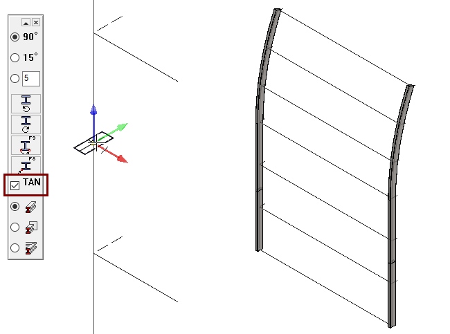
Add vertical profiles
-
Right-click function: Add > Profile.
-
Select the profile from the library Profiles > Thinwall_tub_spar > SSAB_10305_RECTANGULAR.
-
Select size: EN_10305-RECTANGULAR_50X20X2.
-
Note that the Tangentiality selection is valid.
-
Click the vertical lines.
-
Check that the profile is in the position shown.
-
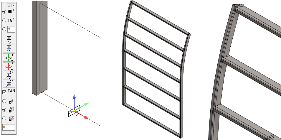
Add horizontal profiles
-
As above, but note the setting: Trim automatically to face.

Check profiles.
-
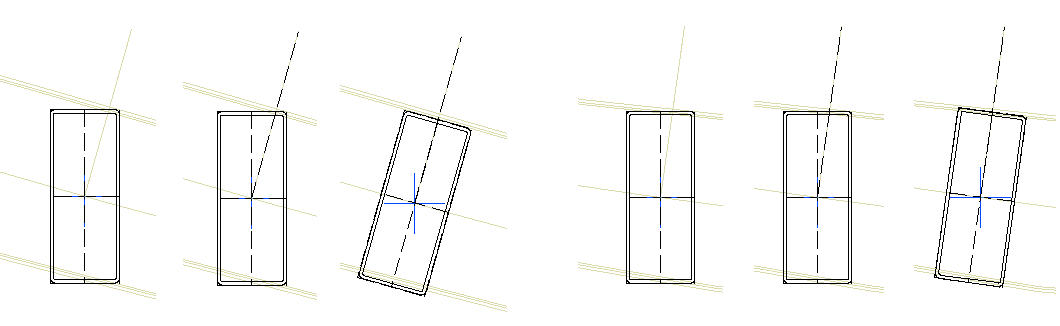
The top three profiles are in the "wrong" position, as they should be tangential to the arc.
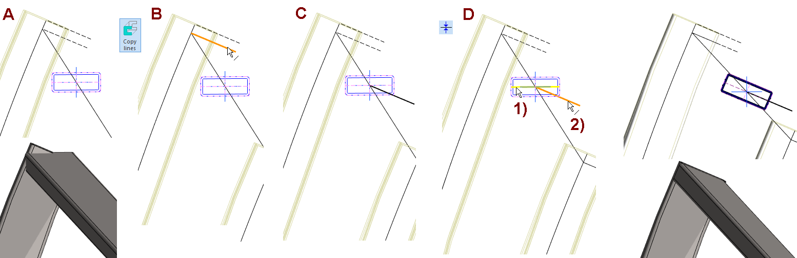
Position the top profile
-
Click on the profile.
-
Right-click function: Edit Profile > Cross Section Sketch.
-
Copy a line from the SKELETON part to the sketch, in figures B and C, for example, with the Copy lines function.
-
Add a coincident constraint between the symmetry line of cross section 1) and the line copied above 2), in the figure D.
-
Exit sketch mode: OK.
Position the next two upper profiles in the same style
Create a drawing for the model
For more detailed instructions, see the Modeling parts course exercise 5 Drawing of Model.
Create a sectional view on the drawing
-
Select a projection.
-
Right-click function: Section View.
-
Click start and end point and stop entering points with OK.
-
Click the section direction and place the section projection.
If you now try to dimension, for example, the spacing of profiles, then it will (by default) succeed.
-
Select the section projection and the right-click function: Properties.
-
Switch from Section to Quick section to Accurate cut.
-
After this, you can also dimension the cutting parts in the section projection.
The keyword sectionviewdefault can be used to determine the quality of the sectional projections generated in a drawing as follows:
-
0 = always an accurate section.
-
1 = quick section for assembly models, exact for part models (This is the default, i.e. valid even if the keyword is missing).
-
2 = quick section for part models, accuracy section for assembly models.
-
3 = always a quick section.
The keyword sectionview_pipes_and_profiles can be used to refine the cutting of profiles and pipes as follows:
-
0 = The keyword “sectionviewdefault” resolves the cutting method. (0 is the default value).
-
1 = Pipes and profiles are cut accurate, even if other geometry is cut quickly.
You can access the keywords: File > System Preferences > Edit > Administrator's View.
-
You can find the keyword in 3d> Default value for fast or accurate section view at drawings based on models.
Create a drawing for the model
For more detailed instructions, see the Modeling parts course exercise 5 Drawing of Model.
Save the model
-
File > Save or click


Download the model (VX_PROF5.vxz) here.