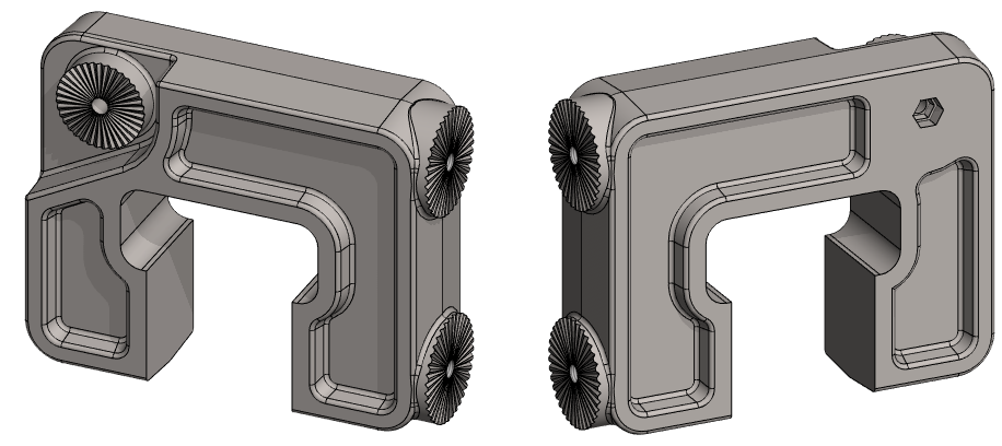
Exercise 4: Sonar body
This exercise was carried out with version 27.0 (Vertex 2021).
In this exercise you will learn to
-
More about sketching tools.
-
Extrude - in Both Directions, To Selected Face.
-
Creating a draft.
-
Geometry dimensional inspection.
-
Create a threaded hole with a cutout feature.
-
Cutout skinning (Loft).
-
Creation of a polar pattern.
-
The use of a sketch feature, i.e., the use of surface edges to aid sketching.
-
To make rounds and rounding chains.
-
Selection of lines behind surfaces.
Functions to be used:
-
Sketching tools, drawing lines and constraints additions.
-
Sketching: Mirror, Offset, Delete Section
-
Draft
-
Round/Bevel > Round.
-
Operation: Boss - Extrude, Cutout - Extrude, Guide Curve, Cross Section.
-
Lofting > Cutout.
-
Pattern.
-
Sketch Feature (interrupted).
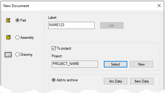
Create a new part
-
File > New > Part.
-
Enter the label (which is also the name of the model and by default will be the name of the drawing).
-
Enter the archive information by clicking Arc.Data.
-
Select the project for the model.
-
OK.
-
Create the first feature
-
New Sketch > To vertical (XZ) plane.
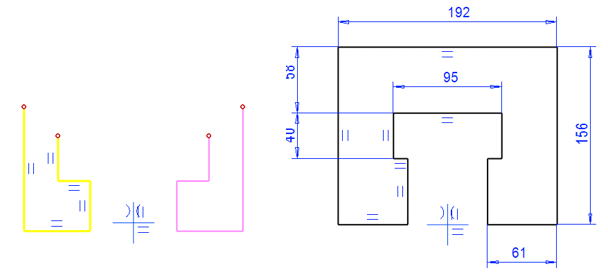
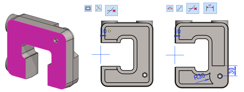
Sketch the shape
-
Sketch the other side (yellow lines, shown in the figure).
-
Mirror them around the center cross.
-
Add missing horizontal lines.
-
Dimension the sketch.
-
Add a coincident constraint between the lowest horizontal line and the horizontal line of central cross.
-
Click

Operation
-
Boss - Extrude - In Both Directions
-
Lenght: 51.
When the extrusion is done in both directions, the Horizontal(XY) Plane remains in the middle of the part, so it can be utilized e.g.
-
In the mirroring of features if they are symmetrical to the auxiliary plane.
-
In symmetrical draft.
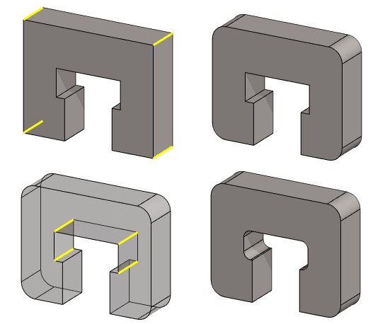
Round the eight corners of the part
-
Click the four outer corners (Use Ctrl key to select several lines)
-
Right-click function: Add Round/Bevel > Round.
-
Radius: 20.
-
In the same way, create the four inner corners a radius of: 10.
-
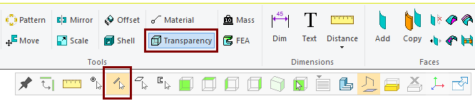
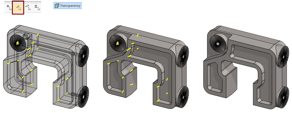
Select: Transparency in the Ribbon.
-
Select Snap to line (no points or faces) in the Tool Strip.
Create the draft in two directions
-
Restore the Vertical (XZ) plane from the feature tree if it is hidden.
-
In the part, select one of the faces to which the draft applies, in the figure 1).
-
Right-click function: Draft.
-
Select reference plane, in the figure 2).
-
Enter the draft angles in the dialog: 5, in the figure 3).
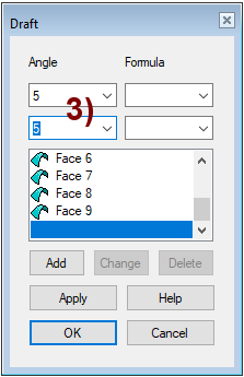
If you select a face with tangential faces as the surface to be drafted, then the program will try to draft them all at once.
The Add, Change, and Delete buttons in the Draft dialog box allow you to edit the set of faces selected for draft.
Create a notch in the frame
-
Select the front face.
-
Right-click function: New Sketch > Face.
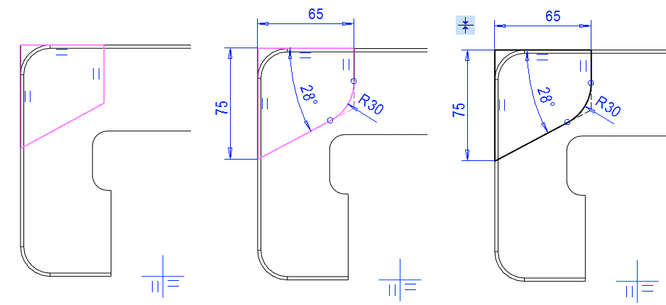
Sketch the shape (trapezoid)
-
Click the first point of the line from the edge of body. (The program adds a coinsident constraint).
-
Sketch the shape and use directional locks if necessary.
-
Add distance and angular constraints.
-
Add rounding.
-
Probably the sketch has not been defined yet.
-
If necessary, add coincident constraint between the sketch lines and the previous geometry.
-
Operation:
-
Cutout - Extrude
-
Lenght: 21.
Remember that the constraint of Distance between two lines always also gives them parallelism (although this constraint parallel is not found separately in the list of constraint).
-
For this reason, it is advisable to use the indication of the lines when giving the distance constraint.
The Distance constraint between two points suggests the shortest distance between them or the vertical or horizontal distance between them, depending on the position of the cursor.
The Dimension constraint suggests a length, horizontal, or vertical dimension to the segment immediately after pointing to the line segment, but allows you to assign a line or point as the second element.
If you are wondering about the behavior of a sketch, i.e., the line "is stuck somewhere where it shouldn't be or the line is not defined even though it should be", then:
-
Cancel operations (Esc key).
-
Click the line.
-
Right-click function: Properties.
-
In the dialog that opens, the constraints that affect the line and its points are explained.
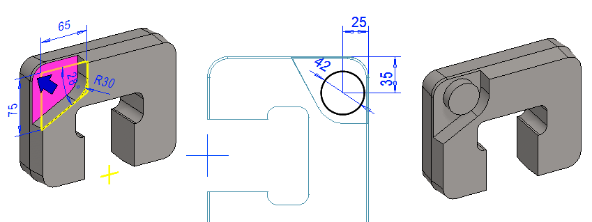
Create the shoulder
-
Select the bottom of the notch.
-
Right-click function: New Sketch > Face.
Sketch the shape
-
The function: Circle. (Circle with Center and Radii Point).
-
Add dimensions.
-
Diameter = 42, Distances are 25 and 35.
-
-
Operation:
-
Boss - Extrude
-
Lenght: 13.
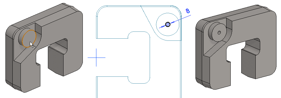
Create the hole
-
Select the shoulder end face.
-
Right-click function: New Sketch > Face.
Sketch the shape
-
The function: Circle. (Circle with Center and Radii Point).
-
Draw a circle so that you click to the center of the shoulder as the center point (the program then adds the concentricity constraint).
-
-
Diameter = 8
-
Operation:
-
Cutout - Extrude -Thru All.
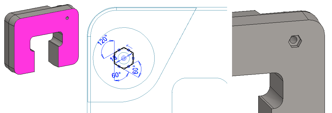
Create the notch for the nut on the back face
-
Turn the part (e.g. the middle mouse button at the bottom).
-
Select the end face of the part.
-
Right-click function: New Sketch > Face.
Sketch the shape
-
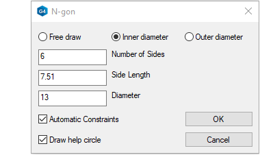
Sketch a hexagon with the function: N-gon.
-
Dimensions suitable for 8mm EN 24032 nut: Inner diameter = 13.
-
Position the hexagon so that the pair of sides come horizontally to the part.
-
-
Operation:
-
Cutout - Extrude
-
Lenght: 6.5 (The thickness of the nut).
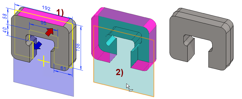
Verify the dimensions of geometry
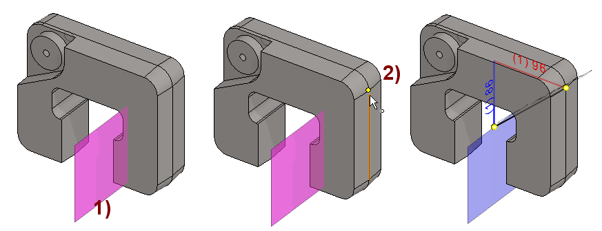
To determine the location of a suitable sketch level, the dimensions of the model are verified:
-
Restore the Lateral(YZ) Plane if it is hidden.
-
The function: Distance (Verify Distance, Shift V)

-
Click the Lateral(YZ) plane, shown in the figure 1).
-
Click to the point on the part, shown in the figure 2).
-
If necessary, you can scale the dimensions larger.
-
-
If you have sketched the frame as symmetrical to the center cross of the first sketch, then the x-direction dimension should be 96 mm.
The distance verify functionality was updated to version 26.0.00 (Vertex 2020).
-
Check out how things were presented then on the page Verify Dimensions 2020
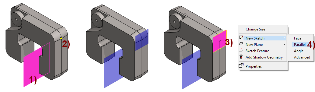
-
Click the Lateral(YZ) plane, shown in the figure 1).
-
Click the point on the part, shown in the figure 2).
-
Right-click function: New Plane.
-
Click the auxiliary Plane, shown in the figure 3).
-
Right-click function: New Sketch > Parallel, in the figure 4).
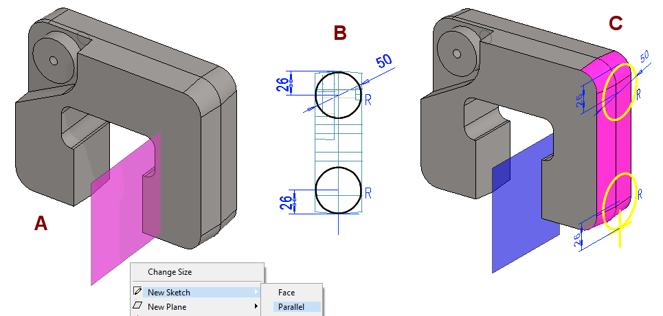
Create the shoulders on the side
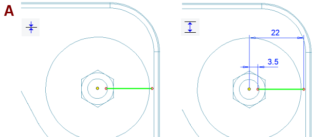
The shoulders extend 4mm from the outermost line of the side i.e. 100mm from the Lateral(YZ) plane.
-
Click the Lateral(YZ) plane, in the figure A.
-
Right-click function: New Sketch > Parallel.
-
Enter value: 100 (Distance from Face).
-
Sketch the circles, shown in the figure B.
-
Point to the center of the line in the geometry (you get the coincident constraint to the line)
-
Add a equal radius constraint to circles.
-
Add a diameter constraint for one circle: 50.
-
Distances of the centers of the circle from below and above: 26.
-
Operation:
-
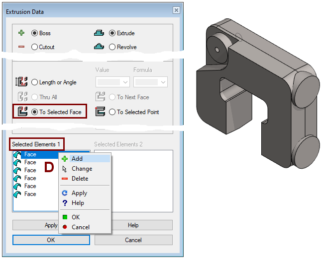
Boss - Extrude - To Selected > Face
-
Hold down the Ctrl key and select the six surfaces shown in Figure C.
-
The "Done" key (= middle mouse button or V key) adds surfaces to the dialog, shown in Figure D.
-
OK completes the extrusion.
Note that the selected set of faces must cover the entire area where the shape of the sketch will extrude.
-
If this does not happen, then the extrusion is indefinite.
In the Selected elements block (in the figure D), you will find a Right-click function that allows you to, for example, add or remove a face if you have first selected it from the list.
Press Apply to see what the extrusion would look like if it were done now.
-
This allows you to check whether you selected enough target faces.
Extrusion can also be done by Length value.
-
Change the direction of extrusion

-
Enter a dimension that is sufficient to extend the extrusion completely inside the part, but does not extend through the part.
Add threaded holes to the end shoulders
-
The function: Cut (Add Cutout using feature from library)

-
Or Right-click function: Library Feature > Cutout.
-
-
Select a feature: Libraries > Features > Standard > Threads > Metric > bore.
-
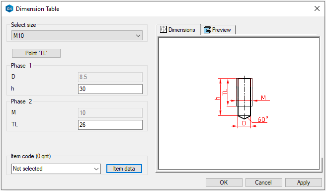
Select the size: M10 and
-
Enter the drilling length h 30 and the thread length TL 26, figure below.
-
OK.
-
-
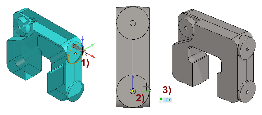
Click the location of the feature.
-
If you clicked at the part so that the cursor says it hits the center of the circle, then the feature is immediately in the right place, in the figure 1).
-
-
Right-click function: Add Feature Copy.
-
Click to the location of the feature copy, shown in the figure 2).
-
Exit from the sketch mode to the part mode with OK, shown in the figure 3).
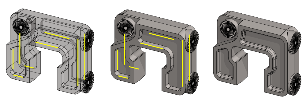
Create a groove
-
A Guide Curve.
-
A Cross Section at both ends of the line.
-
Lofting Cutout with previous elements.
-
Lofting pattern.
Guide Curve, in the figure A.
-
Select the shoulder end face.
-
Right-click function: New Sketch > Face.
Sketch the shape
-
The function: Two Point Line.
-
Add a coincident constraint to the line and the center of the circle.
-
Add the dimensions, as shown
-
Operation:
-
Guide Curve.
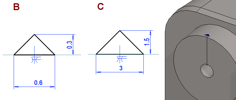
The first cross section, in the figure B:
-
Click the previous Guide curve.
-
Right-click function: New Sketch.
-
Enter Relative position: 0. (The inner end of a line. It can also be 1, depending on how you sketch the line. The 0 end is the end you pointed first, when you drew the line).
-
Sketch the shape
-
The function: Polyline.
-
Sketch a triangle.
-
-
Add a Symmetry constraint between lines, with respect to the center cross.
-
Add a Coincident constraint between the horizontal line and the center cross.
-
Add a Dimension or Distance constraint.
-
Operation:
-
Cross Section.
The second cross section, in the figure C:
-
Click the same Guide curve, than earlier.
-
Right-click function: New Sketch.
-
Enter Relative position: 1. (The inner end of a line. It can also be 0, depending on how you sketch the line).
-
Sketch the shape
-
The function: Polyline.
-
Sketch a triangle.
-
-
Add a Symmetry constraint between lines, with respect to the center cross.
-
Add a Coincident constraint between the horizontal line and the center cross.
-
Add a Dimension or Distance constraint.
-
Operation:
-
Cross Section.
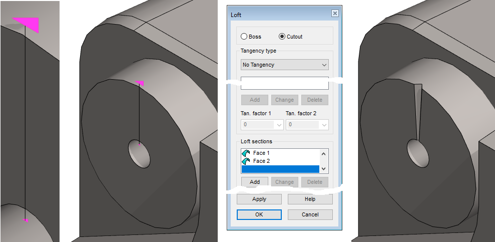
Create a Loft - Cutout, in the figure C:
-
Select both cross sections (Ctrl key)
-
If necessary, zoom in closer so that you can select a cross section rather than lines or points.
-
-
Right-click function: Lofting Cutout.
-
Accept selections (Cutout, No Tangency)
-
OK.
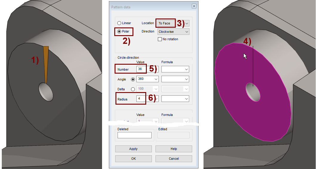
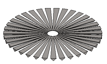
Create a pattern of groove
-
Select the feature from the feature tree, or face of feature, shown in the figure 1).
-
Right-click function: Feature pattern.
-
Select the series type: Polar, shown in the figure 2).
-
Select the location from the list: To Face, shown in the figure 3).
-
Click the surface at the part, shown in the figure 4).
-
Enter the number of members of the pattern, shown in the figure 5).
-
Number: 36.
-
-
Enter the radius, shown in the figure 6).
-
Radius: 4.
-
-
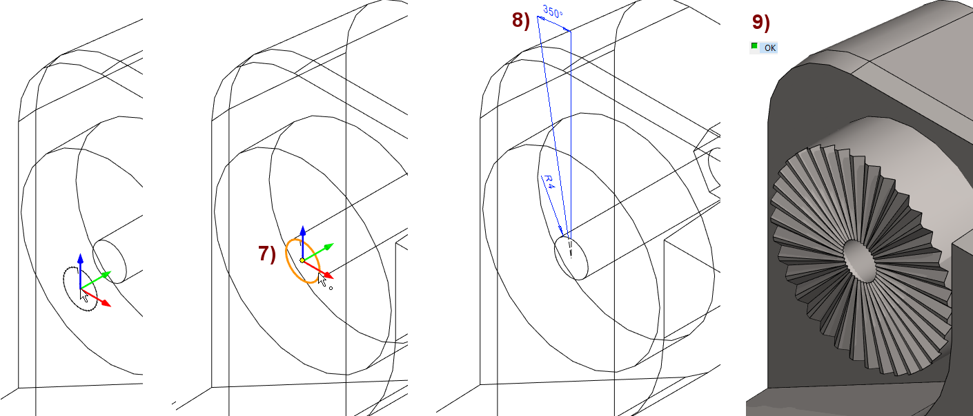
Position the center of the series, shown in the figure 7).
-
This affects both the center of the pattern and the radius of the polar pattern.
-
The program draws dimensions in the sketch, and if necessary you can still dimensions, shown in the figure 8).
-
-
OK, completes the series, shown in the figure 9).
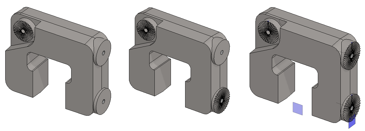
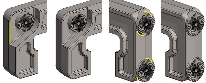
Add similar grooves to other shoulders
-
Repeat the steps learned above.
-
The program adds the auxiliary plane shown in the figure when you need to place a pattern on the indicated face.
-
The G key hides and restores the auxiliary geometry, e.g. these auxiliary levels.
-
As you can see, modeling grooves on those three shoulders is tedious as described above.
It would have been better to use a feature library in this exercise.
-
In the previous exercise "3. Shelf Support” you practiced, how a feature can be stored in a library and read from the library.
For example, such a pattern of groove can be created so that the dimensions of the groove and the number of grooves can be varied while machining the part with the feature.
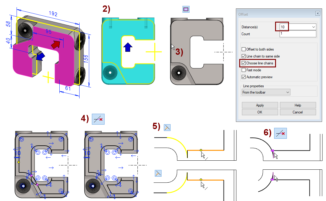
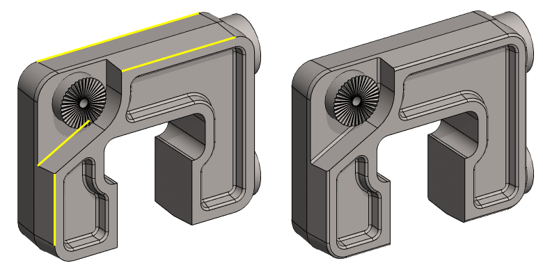
Add a recess to the front of the frame
-
The usual way is to sketch the line chain and dimension the sketch.
-
Another way would be to copy all the face borders to the sketch: Choose lines and a Right-click function: Copy to Sketch Plane. However this is tedious because there are a lot of border lines.
-
The third way is to use the Right-click function: Sketch Feature and pause it to copy all the surface borders to the sketch.
Sketch an offset line (way 3):
-
Select the Face, shown in the figure 1).
-
Right-click function: Sketch Feature.
-
The program copies the edges of face to the sketch and asks for operation, in the figure 2).
-
To cancel the operation, press Cancel or remove the dialog.
-
-
Select all the lines in the sketch by fencing them.
-
Change the properties of the lines to construction line.
-
The function: Offset

-
Change the line style to a Shape line (so that the Offset line is created as a Shape line)
-
Click to a line, in the figure 3).
-
Make sure the Select as chain option is selected.
-
Enter the Distance(s) value: 10.
-
Select the direction of the offset lines inside the chain.
-
OK.
-
Clean offset lines:
-
Remove extra sections from the lines, shown in the figure 4).
-
Trim the line to the arc, shown in the figure 5).
-
Note that you must either restart the function, or use the "Done" key (V key or Middle Mouse Button) before pointing the second arc as the target line, as the program allows you to trim multiple lines up to the target line at once.
-
-
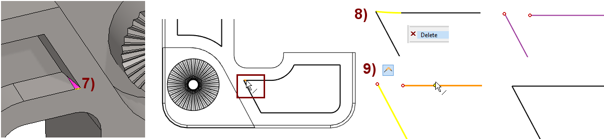
Remove extra sections from the lines, shown in the figure 6).
If the extrusion were done now, then the small face (shown in the figure 7) would be left in the part, which would prevent rounding from being done later.
-
Delete the arc, shown in the figure 8).
-
Trim the lines together, shown in the figure 9).
-
Operation:
-
Cutout - Extrude
-
Lenght: 10
-
Dfart Angle: -10.
Assume: You made an accidental Boss > Extrude operation when when you had to do Cutout > Extrude operation.
Fixed operation:
-
Click to Extrusion from the feature tree.
-
Right-click function: Edit Operation.
-
Change Boss to Cutout.
Create a recess on the other side as well
-
Click the back face.
-
Right-click function: Sketch Feature.
-
Change lines to construction line.
-
Add offset lines.
-
Sketch an arc and a line segment.
-
Trim and cut lines.
-
Add dimensions
Operation:
-
Cutout - Extrude
-
Lenght: 10
-
Dfart Angle: -10.
Create roundings on individual edges
-
Select the individual sharp edges, shown in the figure. (Remember the Ctrl key)
-
Right-click function: Add Round/Bevel > Round
-
Enter the value: 6.
In this exercise, you will have to turn the part when selecting the edges to be rounded.
-
Press the middle mouse button and calmly move the cursor.
-
Or press the Shift key and press and hold the mouse selection key and move the cursor calmly.
Before selecting a new line after turning, remember to press the Ctrl key.
-
Without the Ctrl key, previously selected lines will be dropped from the selections.
The Round function seeks to find a chain of tangential lines and to make a rounding between the faces resting on this chain at once.
The Single Edge Round seeks to round only between faces that rest on a selected line.
-
In the dialog, you can control the roundings of each selected edge individually.
-
However, it is easier to select the edges with same rounding value at once. This is especially the case when different values are tested for roundings.
One or more edges can be selected for both functions.
-
In some cases, it is advisable to round first to only one chain at a time, as the solution of "colliding" chains may not always be successful.
If you forgot to select an edge, it is recommended that you add it to the same Rounding / Bevel history step and don't do a new rounding.
-
This makes the feature tree of the model shorter and the regeneration of the model history is a bit faster.
Here's how to add an Edge to an existing Round/Bevel feature:
-
Select the Round/Bevel feature from the feature tree.
-
Right-click function: Edit operation.
-
Hold down the Ctrl key and
-
Click to the edge of the model.
-
Accept or enter the rounding radius.
-
OK.
Create rounding chains
-
Select one edge from each "chain".
-
Right-click function: Add Round/Bevel > Round.
-
Enter the value: 2.
-
-
Select one edge from each "chain".
-
Right-click function: Add Round/Bevel > Round.
-
Enter the value: 2.
-
-
Select one edge from each "chain".
-
You have to click two lines on both shoulders (A pair of figures on the right).
-
Right-click function: Add Round/Bevel > Round.
-
Enter the value: 2.
-
Save the model
-
File > Save or click


Adding part item data and creating and processing a model drawing is handled in the next exercise.