

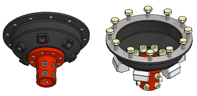
Exercise 4: Part patterns
This exercise was carried out with version 27.0 (Vertex 2021).
In this exercise you will learn to
-
To add components and parts to a pattern that is determined by the feature pattern in the parts.
-
To add a handle to the part that makes it easier to position the part in the assembly.
Functions to be used:
-
Add > Model, And > Component.
-
Constraints > Concentricity, Parallel.
-
(Part:) Add Handle.
-
(Assembly:) Pattern.
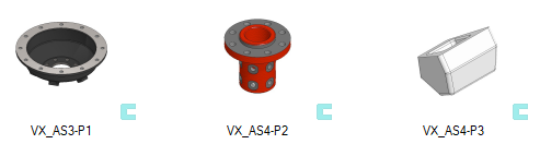
Get a project that includes the necessary parts
-
Download the zipped Vertex project (VX_AS4_PARTS.vxz) here.
-
Drag the file from the downloads section of your Internet browser onto Vertex G4.
-
Be sure the models are found (in browser B) in project VX_COURSE_ASSY.
-
If necessary, refresh your browser, if those models VX_AS4-P* are not found immediately.
-
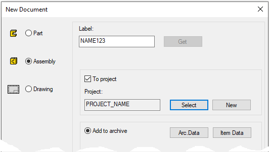
Create a new assembly
-
File > New > Assembly.
-
Enter the label (which is also the name of the model and by default will be the name of the drawing).
-
Enter the archive information by clicking Arc.Data.
-
Select the project where the model will be saved.
-
OK.
-
Add parts from the archive to the assembly
-
First add the drum (VX_AS4-P1).
-
It can be found under project VX_COURSE_ASSY.
-
For example, with right-click function Add > Model or with the B browser.
-
Drop the part into place, for example, with the middle mouse button.
-
-
Then add the support sleeve (VX_AS4-P2) and the damper (VX_AS4-P3).
-

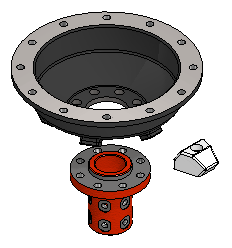
Connect the drum (VX_AS4-P1) and the support sleeve (VX_AS4-P2) with constraints
-
Add two concentricity constraints and one coincitence constraint between the parts.
Damber pad constraints
-
You can try positioning the damber pad to drum with constraints. You need three constraints for it, e.g., concentricity and a couple of coincitence constraints.
-
But in this exercise, we add a handle to the part that allows the damper pad to locates better and requires only one constraint.
Version 27.0.00 introduced the ability to position parts using preselectedconstraints added to them.
Version 28.0.00 introduced an artificial intelligence-based way to add constraints.
Neither of these methods has been used in this exercise.
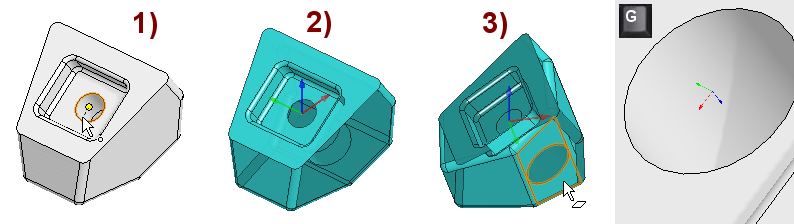
Add a handle to the damber pad
-
Open the damber pad model VX_AS4-P3 (in its own window) , eg with a B browser.
-
Select the center point of the hole, in the figure 1).
-
Right-click function: Add Handle.
-
A coordinate system symbolizing the handle appears on the model and the program prompts: Location point connection: Show Z -direction plane or 1st point. In the figure 2).
-
-
Turn the model so far that you can point to the underside of the damber.
-
The blue axis, which later determines the direction of the part when positioning the part, is directed towards the indicated plane.
-
-
Save the model VX_AS4-P3 and remove it from the Vertex desktop.
The surface in which the blue axis of the handle is oriented normal (i.e. perpendicular) must be found in the model.
If not, add an New Plane that is in the right direction.
-
The orientation of the blue axis then depends on which side of the Plane the binding would be indicated.
The handle of the components (and features) is important because it makes it easier to place the components in the assembly.
The handle can also be used in part (as in this exercise) as an aid to placement.
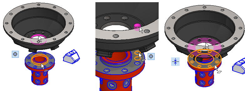
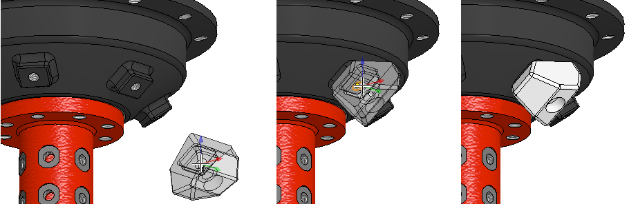
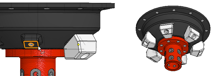
Add a damper pad to the protrusion of the drum
-
If you added a damper pad before, delete it.
-
Add > Model: VX_AS4-P3.
-
Move the cursor over the geometry. You will see that the direction of the part changes.
-
Move the cursor over the threaded hole of protrusion, so that the center of the hole is selected and click to the location.
-
When asked Greate pattern, answer: No.
-
Because the damber pad is (probably) in the wrong position.
-
-
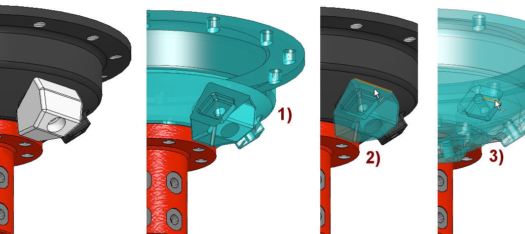
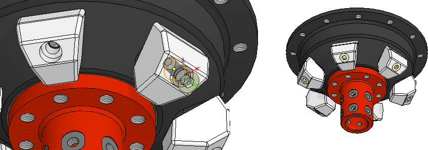
Drag (rotate) the damper pad and position it with constraint
-
Grasp the damber and rotate it in approximately the correct direction.
-
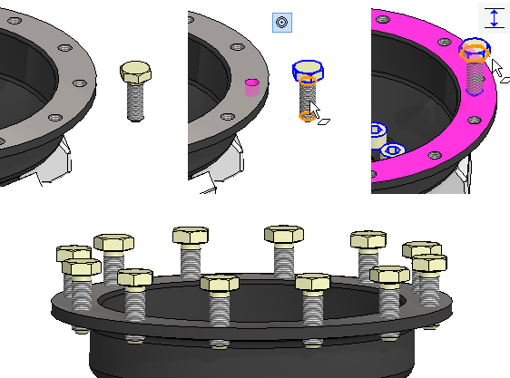
Select the drum and damper pad (note the latter Ctrl key at the bottom), in the figure 1).
-
Select the Parallel constraint.
-
The program warning: Assembly is arready fully defined, add constraint anyway? (This is not entirely true in this case. The handle is usually used in components whose rotation is irrelevant, so the degree of freedom of rotation is usually not taken into account when assessing the completeness of the assembly constraints).
-
Answer: Yes.
-
-
The program will color the damper pad (if you selected it last).
-
Click on the line, in the figure 2).
-
The program will color the drum (if you selected it first).
-
Click on the line, in the figure 3).
Create a patter from damber pads
-
Choose a damber pad (VX_AS4-P3) from either the model or the feature tree.
-
Right-click function: Pattern.
-
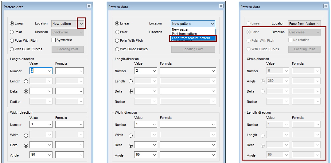
The Pattern data dialog opens.
-
-
Under Location, select: Face from feature pattern.
-
Click to any surface of the drum protrusion.
-
The program shown the data of the pattern (the figure of the dialog on the right).
-
OK creates a pattern.
Insert a hex socket screw into the damper pad
-
Right-click function: Add > Component.
-
Components > Standard > Fastener > Screws > Regular_Thread > DIN-EN_ISO_4762.
-
-
Select diameter: 8 and length 20 in the following dialog (DIN-EN_ISO_4762-M8X20)
-
Click to the center point of the hole in the damper bad.
-
When asked Greate pattern, answer: Yes.
Insert the hex socket screw to fix the drum and support sleeve
-
Right-click function: Add > Component.
-
Components > Standard > Fastener > Screws > Regular_Thread > DIN-EN_ISO_4762.
-
-
Select diameter: 10 and length 16 in the following dialog (DIN-EN_ISO_4762-M10X16)
-
Click to the center point of the hole.
-
When asked Greate pattern, answer: Yes.
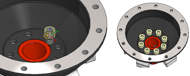
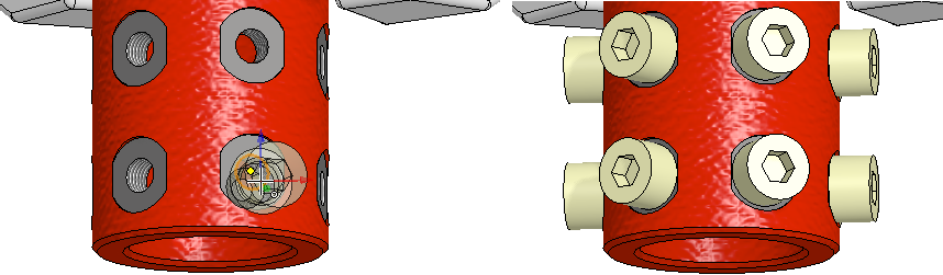
Add the hex screw, Position it, and then create a pattern
-
Right-click function: Add > Component.
-
Components > Standard > Fastener > Screws > Regular_Thread > DIN-EN_24017.
-
-
Select diameter: 10 and length 30.
-
Place the screw in space.
-
Position it with concentricity and distance constraints in the hole.
-
Distance: 18.
-
-
Click the screw and the right-click function: Pattern.
-
Location: Face from feature pattern.
-
Click the face of hole.
-
Accept the dialog values.
In our standard components, the handle is positioned so that the cylindrical part of the screw sinks completely into the hole.
If necessary, a construction line could be added to the screw, at the end of which a handle would be placed, and the distance of the screw head from the surface of the hole would be adjusted along the length of the construction line.
As of version 27.0.00 (Vertex 2021), instead of a handle, pre-selected constraints could be placed on the screw to adjust the height of the screw head from the surface.
Insert the hex socket screw into the support sleeve
-
Right-click function: Add > Component.
-
Components > Standard > Fastener > Screws > Regular_Thread > DIN-EN_ISO_4762.
-
-
Select diameter: 8 and length 10 in the following dialog (DIN-EN_ISO_4762-M8X10)
-
Click to the center point of the hole.
-
When asked Greate pattern, answer: Yes.
If the holes in the top surface of the drum had been made as a pattern of sketches, then:
-
A thread mark should have been added separately to each hole.
-
When the screw was added, the program would not have suggested making a pattern.
Save the model
-
File > Save or click


Download the model (VX_AS4.vxz) here.