

Exercise 4. Base
This exercise was carried out with version 27.0 (Vertex 2021).
In this exercise you will learn to
-
Trimming of profiles to the face.
-
Cut a profile into two profiles.
-
Merge two profiles into one profile.
Functions to be used:
-
New local part of the assembly.
-
Sketching: Two-point rectangle, Two-point line and dimensioning.
-
Add > Profile.
-
Cut profile.
-
Merge profiles.
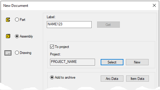
Create a new assembly
-
File > New > Assembly.
-
Enter the label (which is also the name of the model and by default will be the name of the drawing).
-
Enter the archive information by clicking Arc.Data.
-
Select the project where the model will be saved.
-
OK.
-
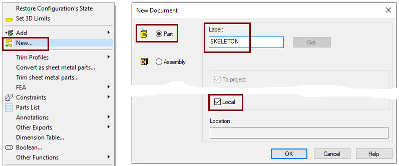
Create a new local part (Skeleton - Guide curve)
-
Right-click function: New > Part
-
Enter a name, eg SKELETON or JIG
-
.
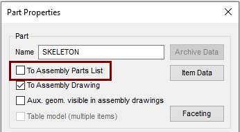
Define that the control curve part does not appear in the parts list
-
Right-click function: Properties
-
Deselect the settings: To Assembly Parts list, because this part is not desired in the parts list, after all it is a completely "intangible" part.
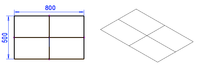
Sketch the skeleton (guide curve)
-
Right-click function: New Sketch > To horizontal (XY) plane.
-
Sketch a rectangle of symmetries for the central cross.
-
Add dimensions: 800 and 600.
-
Sketch lines between the centers of the lines.
Operation:
-
Guide curve
Exit from part to assembly
-
OK.
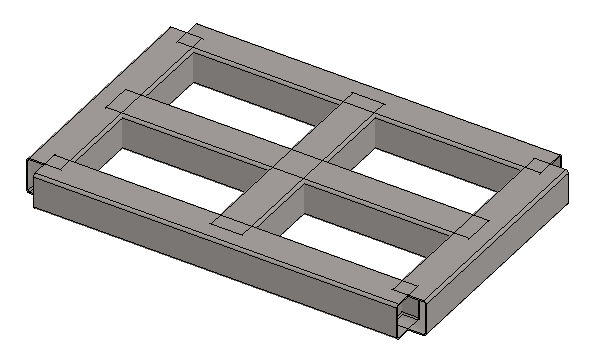
Add all profiles without the trim option
-
Right-click function: Add > Profile.
-
Select the profile from the library Profiles > Thinwall_tub_spar > SSAB_10219_SQUARE.
-
Select size: SSAB_80x80x2.
-
Select the trimming mode: Don't trim automatically

-
Add a profile for all guide lines.
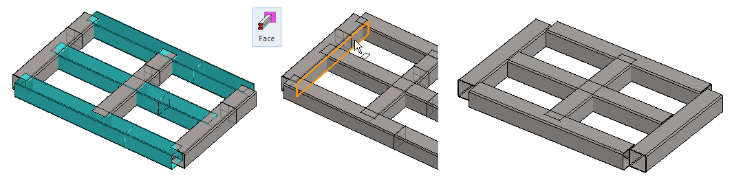
Trim long profiles to the face of the end profiles.
-
Click long profiles (The latters at the

-
The function: Face from the ribbon.
-
Click to the inside face of the traget profile.
-
OK completes trimming.
-
Do the same for the other end.
Trim the end profiles to the outer face of the side profiles
-
Click end profiles.
-
The function: Face from the ribbon.
-
Click to the out face of the side profile.
-
OK completes trimming.
Do the same for the other end.

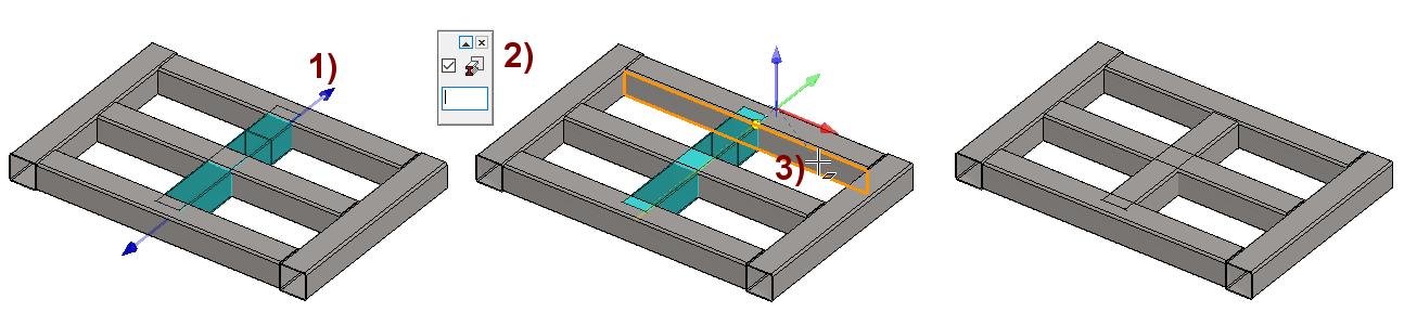
Stretch the short center profile to the inner faces of the side profiles
-
Click the profile you want to stretch (shorten).
-
If the profile is not trimmed, blue arrows or "pull handles" will appear at the ends of the profile.
-
Click the blue arrow on the head to be trimmed, in the figure 1).
-
If you want the end of the profile to be stretched to have an associative connection to the indicated target surface, select Trim automatically to face in the upper left corner of the desktop. If necessary, you can give a trimming gap, in the figure 2).
-
Click to the target face, in the figure 3).
-
Do the same on the other end of the profile.
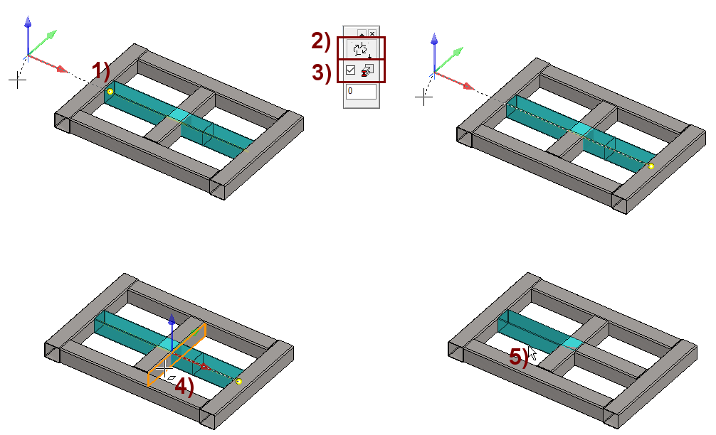
Cut the long middle profile
Cut the long center profile so that it trims to the face of the short center profile.
-
Click on the profile.
-
Right-click function: Cut profile or function

-
The program marks with a yellow dot the end from which you start towards the cutting point, in the figure 1).
-
-
If necessary, replace the start end with the button in the upper left corner of the desktop, in the figure 2).
-
If you want the end of the profile to be stretched to have an associative connection to the indicated target face, then select
Trim automatically to face, in the Figure 3).
-
Click to the target face, in the figure 4).
If you now select the other half of the center profile, in the figure 5), you will see that it overlaps with the short center profile.
-
In the same way as described above.
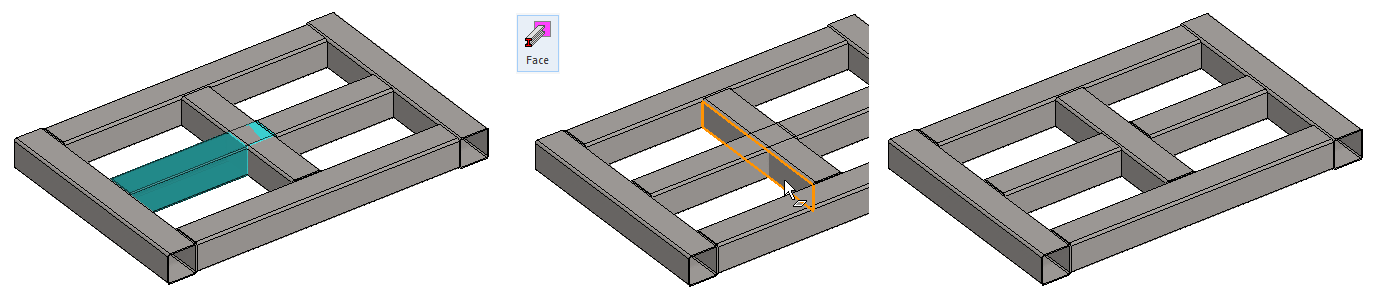
Trim the center profile so that the profiles do not collide
-
Click on the profile.
-
The function: Face from the ribbon.
-
Click to the out face of the target profile.
-
OK completes trimming.
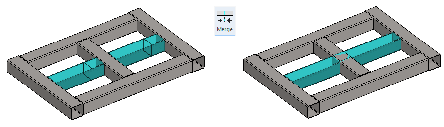
The plan changes
It is desired that the long middle profile be uniform and the short one truncated.
Merge two profiles into one profile
-
Click Profiles to merge (Remember
-
Right-click function: Merge profiles or function Merge from the ribbon.
Only similar profiles can be merged.
-
You cannot merge, for example, a U-beam and an I-beam.
-
You cannot merge the D100 and D80 thin-wall tup-sbar.
-
You cannot merge profiles that are not on the same line.
If the profiles of the same size to be joined are in a different rotations, e.g. the second one was rotated about its axis by 15 degrees, then the joined profile is in the position in which the profile selected as the first profile to be joined was.
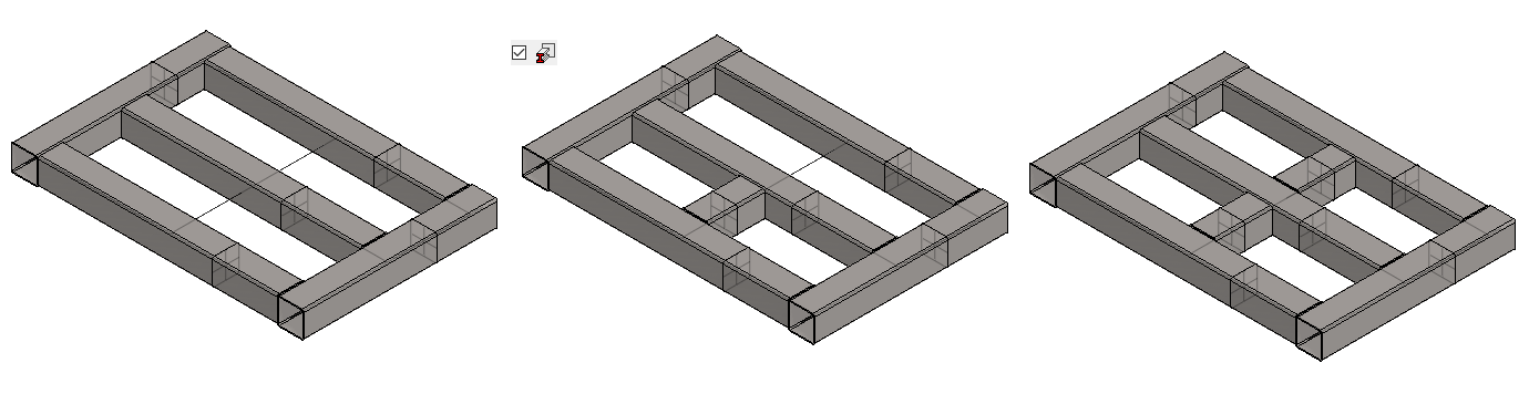
Process a short profile
You can cut a short profile first. You can then trim the longer half to the face of the center profile.
-
See previous instructions.
But in this case, when no more special changes have been made to the center profiles, such as rotations around their guide line or trimming of the heads to parts or more surfaces, it may be easier to delete the profile and re-add the profiles, taking into account automatic trimming of the face:
-
Click the profile and press key Delete or the right-click function Delete.
-
Click the center profile and the right-click function: Add > Same Profile.
-
Switch to trimming mode on the: Trim automatically to face.

-
-
Click on the control curve on both sides of the center profile.
Create a drawing for the model
For more detailed instructions, see the Modeling parts course exercise 5 Drawing of Model.
Save the model
-
File > Save or click


Download the Base model (VX_PROF4.vxz) here.