

Exercise 3: V-engine
This exercise was carried out with version 27.0 (Vertex 2021).
In this exercise you will learn to
-
Build assemblies from parts and assemblies.
-
To locate parts with each other using constraints.
-
To add a component to a pattern because the part has a feature pattern.
-
To simulate a model (movement of pistons).
-
To add constraints between the two parts without the other parts in front or the faces of the other part interfering with the clicking.
-
Manage sub-assembly configurations using main assembly configurations.
-
To add an auxiliary plane in the part model using three points.
-
To control the freezing of subassemblies in the main assembly (i.e., whether the constraints of the subassembly are resolved while the constraints of the main assembly are resolved).
-
To simulate measurement (distance and angle) constraints.
Not all selections or keystrokes are presented in this exercise as accurately as in the previous exercise, so if you are surprised by the addition of parts or conditions, then see the second exercise for more detailed procedures.
Functions to be used:
-
Add > Model. Add > Component.
-
Constraints: Concentricity, Coincidence, Parallel, Angle.
-
Configurations > Add Configuration, Properties.
-
Hiding > Hiding at configurations.
-
Distance > Distance.
-
Change a configuration.
-
(Part model, three points selected:) New plane.
-
In assembly and in subassembly: Properties.
-
In assemble (distance or angle constraints:) Simulate.
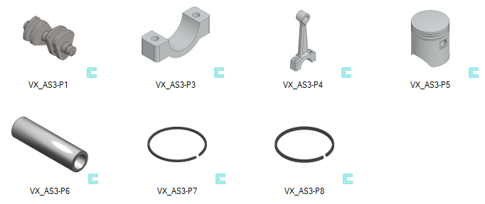
Get a project that includes the necessary parts
-
Download the Vertex project zip VX_AS3_PARTS.vxz here.
-
Drag the file from the downloads section of your Internet browser onto Vertex G4.
-
Be sure the models are found (in browser B) in project VX_COURSE_ASSY.
-
If necessary, refresh your browser, if those models VX_AS2-P* are not found immediately.
-
Model the lowest level assemblies
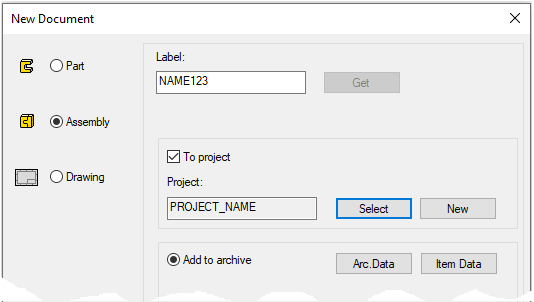
Create a new assembly (Connecting rod)
-
File > New > Assembly.
-
Enter the label (which is also the name of the model and by default will be the name of the drawing).
-
Enter the archive information by clicking Arc.Data.
-
Select the project where the model will be saved.
-
OK.
-
Add the parts of connecin rod from archive
-
First add the base of the connecting rod (VX_AS3-P3).
-
Right-click function: Add > Model or with B browser.
-
Part can be found inside the project VX_COURSE_ASSY.
-
Drop into place, for example, with the middle mouse button.
-
-
Then add the connecting rod (VX_AS3-P4).
Put the parts together using the constraints.
-
Three constraints have been used in the figure above:
-
Coincidence of planar faces.
-
Consentricity of cylindrical faces.
-
Coincidence of lines.
-
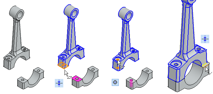
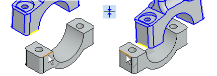
Two constraints have been used in the bottom figure that drive the same things as the three constraints in the top figure:
-
Two Coincidence constraints is placed between the two pairs of lines.
Alternative way:
Add washers
-
Add the star plate DIN_6798A, size 8.4.
-
Available from the library: Fasteners > Washers > DIN_6798-A.
-
Right-click function: Add > Component or with B browser.
-
-
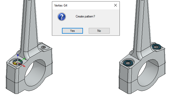
Click to the top of the crank hole (in the left figure).
-
Note the position indication so that there is a correct face below and that its center point is selected.
-
If not, the star plate will go in the wrong place
-
-
Because the program detects that a feature pattern has been used in the part, the program asks: Create pattern?
-
Answer: Yes.
-
-
Click to another place below and let the program do the pattern there too.
When a part is being added to an assembly so that the feature pattern of the part model is found at the indicated point, the program allows the part to be added to the pattern based on that feature pattern.
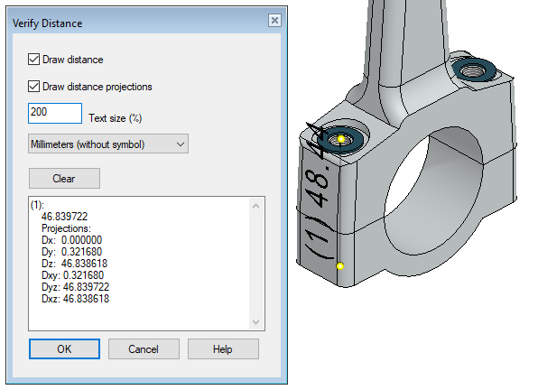
Measure the length of the required screw
-
Function (in the ribbon): Distance >Distance.
-
Click points or faces at the extreme surfaces of the washers.
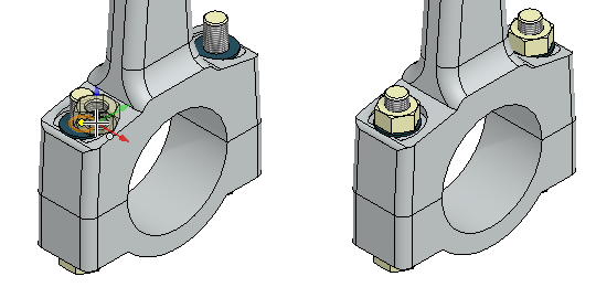
Add screws
-
Add fine thread screw DIN_EN_28765, size M8 length 60.
-
Available from the library: Fasteners > Screws > Fine_Thread > DIN_EN_28765.
-
Right-click function: Add > Component or with B browser.
-
-
Click to the location on the washer of the connecting rod (in the left figure).
-
Because the program detects that a part pattern has been used, the program asks: Create pattern?
-
Answer: Yes.
-
When a part is being added to an assembly so that the pattern of the parts is found at the indicated point, the program allows the part to be added to the pattern based on pattern of part.
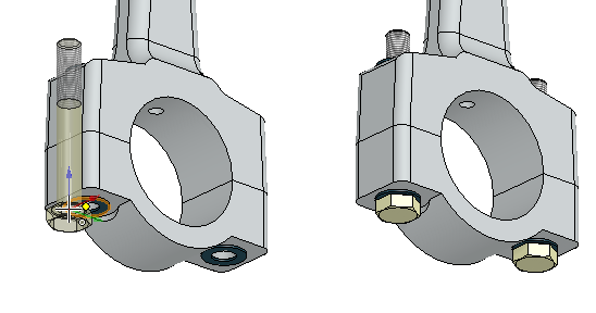
Add nuts
-
Add fine thread nut DIN_EN_28673_28674, size M8.
-
Available from the library: Fasteners > Nuts > Fine_Thread > DIN_EN_28673_28674.
-
Right-click function: Add > Component or with B browser.
-
-
Click to the location on the washer of the connecting rod (in the left figure).
-
Because the program detects that a part pattern has been used, the program asks: Create pattern?
-
Answer: Yes.
-
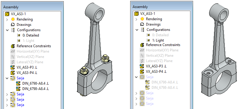
Create a new confuguration and hide the components from it
-
Click Confuguration (from the feature tree).
-
Right-click function: Add Configuration.
-
Enter the name of the configuration: Light.
-
Click the first confuguration 0: Default and right-click function: Properties.
-
Rename it: Detailed.
-
Select all components in the feature tree.
-
Right-click function: Hiding > Hiding at configurations.
-
Select the confuguration: 1: Light.
Save the model
-
File > Save or click


Create a new assembly (Piston)
-
File > New > Assembly.
-
Enter the label (which is also the name of the model and by default will be the name of the drawing).
-
Enter the archive information by clicking Arc.Data.
-
Approve the proposed project.
-
OK.
-
Add parts of piston from the archive
-
First add the piston (VX_AS3-P5).
-
Right-click function: Add > Model or with B browser.
-
Drop the first part into place with mouse middle button.
-
Press the middle mouse button again and the program will search for the next model.
-
-
Add parts: VX_AS3-P6 (piston pin), pair VX_AS3-P7 (piston ring) and VX_AS3-P8 (oil ring).
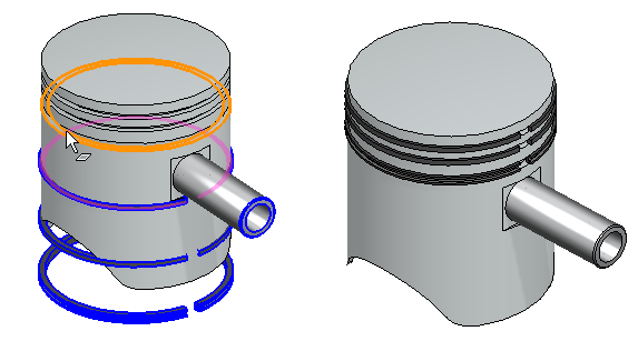
Add constraints.
-
The concentricity between the piston and the rings and between the piston and the pin.
-
Coincidence between the lower surface of the rings and the lower surface of the grooves of the piston rings.
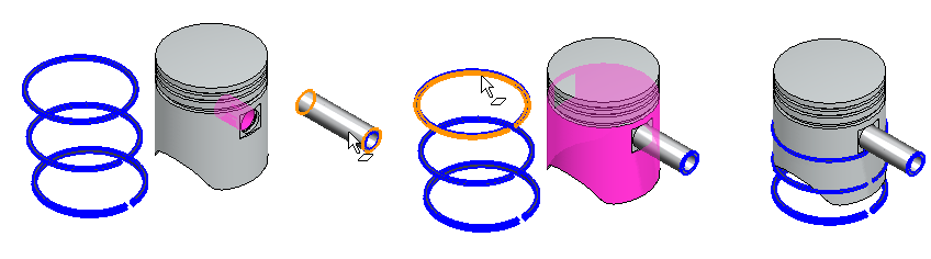
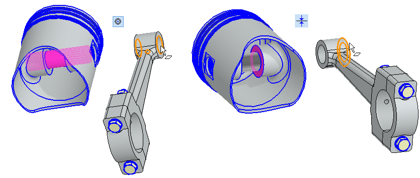
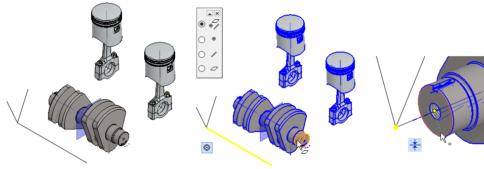
Add a constraint between the piston and the pin
-
Click to the piston and its pin. (Remember Crtl key).
-
Function: Coincidence (from to ribbon).
-
The program colors the latter part (piston pin) and waits for you click the face at it.
-
Click face (pin end face).
-
-
The program colors the first part (piston) and waits for you to click the face at it.
-
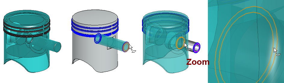
Click to the surface (inner face of the pin ring groove).
-
That face can be tricky to spot, so zooming will help.
-
If the parts in front or the faces of the parts interfere with the adding of the conditions, then:
-
First select the parts.
-
Then select a constraint (either from the ribbon or right-click function: Constraints > ...)
-
The program stains the part with attention color.
-
-
Click on the highlighted element (face, line, or point).
-
The program stains the part with attention color.
-
-
Click on the highlighted element (face, line, or point).
-
You can to continue clicking elements or
-
Change the constraints with a right-click function: Conditions > ...)
-
-
Stop giving constraints between these two parts with:
-
the middle mouse button or


-
An alternative way: Drag the pin to a new location and then add the constraint (In the bottom figure).
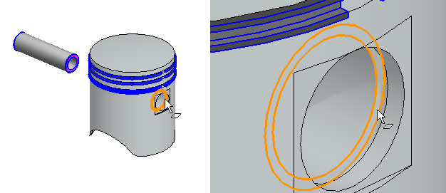
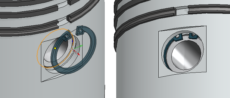
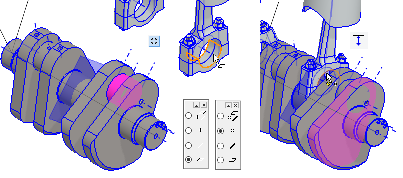
Insert the circlip into the grooves on the piston pin
-
Add the circlip (Seeger ring) DIN_472-8_25, size 23 at both ends of piston pin.
-
Use the right-click function Add > Component (or the B browser or the Add function on the ribbon).
-
Choose from the Library (Libraries> Components > Standard >) Shaft_Parts > Locking_Elements > DIN_472-8_25.
-
-
Note the position indication so that below is the correct face whose center point should be selected.
-
If not, the circlip will go in the wrong place.
-
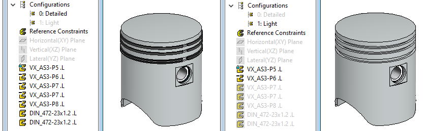
Create another configuration and hide the piston rings and circlips from it
-
Click Confuguration (from the feature tree).
-
Right-click function: Add Configuration.
-
Enter the name of the configuration: Light.
-
Click the first confuguration 0: Default and right-click function: Properties.
-
Rename it: Detailed.
-
Select all components from the feature tree.
-
Click the first component in the list.
-
Press the

-
-
Right-click function: Hiding > Hiding at configurations.
-
Select the confuguration: 1: Light.
Save the model
-
File > Save or click
Model the assembly from the assemblies.
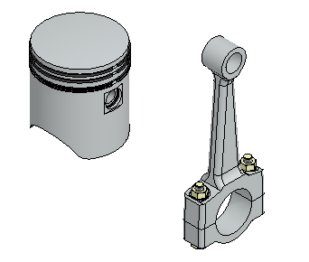
Create a new assembly (Piston + connecting rod)
-
File > New > Assembly.
-
Enter the label (which is also the name of the model and by default will be the name of the drawing).
-
Enter the archive information by clicking Arc.Data.
-
Approve the proposed project
-
OK.
-
Add connecting rod and piston assemblies
-
First add the connecting rod and then the piston. Add detailed configuration of them.
-
The connecting rod is then fixed by default.
-
Add the connecting rod to the origo of the assembly (Drop in place eg.

-
-
Add the piston to the air.
Place the piston on the connecting rod
-
Add the Concentricity constraint between the piston pin and the connecting rod loop.
-
Add the Coincidence constraint between the piston and the connecting rod.
Drag a parts
-
The connecting rod does not move (it is fixed in place, the feature tree symbol has a blue lock).
-
The piston rotates around the pin.
Create another configurations and connect the configurations of sub assemblies to the main configurations of assembly.
Here it is intended to form two configurations in the main assembly, detailed and light. The detailed configuration shows all the parts and the light configuration shows the parts that appear in their sub-assembly in their lightened configuration.
-
Click Confuguration (from the feature tree).
-
Right-click function: Add Configuration.
-
Enter the name of the configuration: Light.
-
Click the first confuguration 0: Default and right-click function: Properties.
-
Rename it: Detailed.
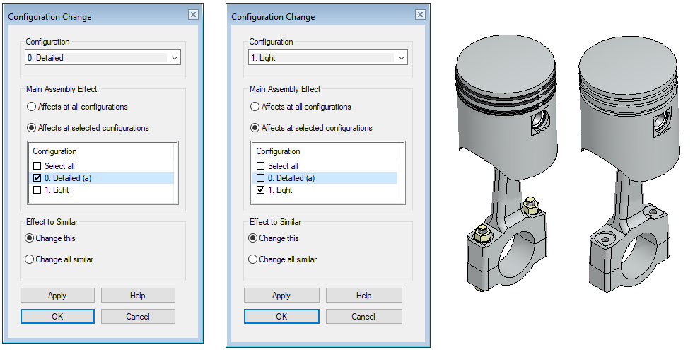
Connect the configurations of sub assemblies to the main configurations of assembly.
-
Select the assembly of connecting rod from the feature tree.
-
Right-click function: Change configuration.
-
Select the appearance of the connection rod (from the top row): Detailed.
-
Select: Affects at selected configurations. (in the main assembly).
-
Select the configuration of the main assembly: Detailed.
-
Press Apply.
-
-
repeat the same for the other connection rod configuration:
-
Select the appearance of the connection rod (from the top row): Light.
-
Select: Affects at selected configurations. (in the main assembly).
-
Select the configuration of the main assembly: Light.
-
Press Apply.
-
OK.
-
-
Select the assembly of piston from the feature tree.
-
Do the same as above.
-
Connect the detailed configuration of the piston to the detailed configuration of the main assembly and the light configuration of the piston to the light configuration of the main assembly.
-
Test the configurations of the assembly.
-
Double-click each configurations to activate it in turn.
-
Both subassemblies should then show an detailed or light model.
Save the model
-
File > Save or click
Model the main assembly
Create a new assembly (engine)
-
File > New > Assembly.
-
Enter the label (which is also the name of the model and by default will be the name of the drawing).
-
Enter the archive information by clicking Arc.Data.
-
Approve the proposed project
-
OK.
-
Create a local part (guide curve)
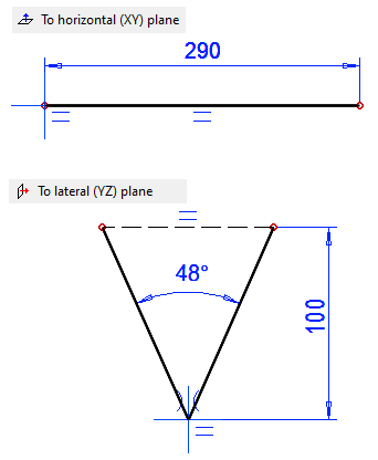
Since no blocks or oil sumps have been modeled for this exercise, a steering curve section is made from which the crankshaft is positioned and whose geometry is used to guide the direction of movement of the pistons.
-
Right-click function: New > Part > Local, Enter a name, eg SKELETON.
-
Right-click function: New Sketch > To horizontal (XY) plane.
-
Sketch a horizontal line and dimension it: 290.
-
Start at the origo.
-
-
Operation: Guide curve.
-
Right-click function: New Sketch > To lateral (YZ) plane.
-
Sketch the lines according to the figure below and dimension them.
-
The oblique lines are symmetrical about the vertical axis of the central cross.
-
Horizontal line type: Construction.
-
-
Operation: Guide curve.
-
Exit from part to assembly: OK.
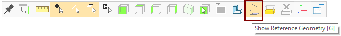
You can display the auxiliary geometry (guide lines, auxiliary planes and cross sections) with the G key or the Show Reference Geometry function of the Tool Strip:
Add the crankshaft and the assembly modeled above to the assembly
-
Add Crankshaft (VX_AS3-P1).
-
Add the piston connection rod assembly twice.
Position the Crankshaft in the guide curve
-
Add the Concentricity constraint between the horizontal line of the SKELETON section and the cylindrical surface of the crankshaft.
-
Add the Coincidence constraint between the intersection point of the SKELETON and the center of the end of the crankshaft.
Drag (Rotate) the crankshaft
-
It rotates in place.
Position the connecting rods on the crankshaft
-
Add the Concentricity constraint between the cylindrical surface of the crankshaft and the cylindrical surface of the connecting rod (or the center line drawn on its axis).
-
Add the Diameter constraint 1, between the crankshaft flange and the end point of the connecting rod.
With auxiliary menu functions: Snap to face, Snap to line and Snap to point.
Drag (Rotate) the crankshaft
-
The connecting rod-piston assembly rotates rigidly.
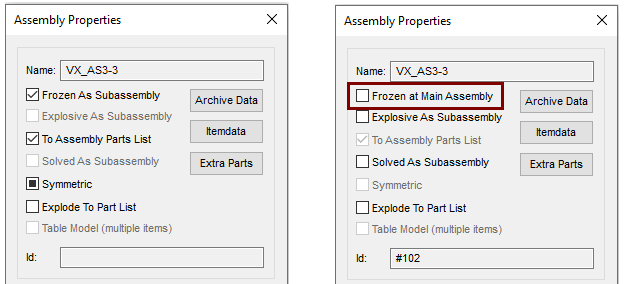
Remove the freeze from the subassemblies
-
Select the connecting rod-piston assembly in the feature tree.
-
Right-click function: Properties.
-
The program opens the dialog: Assembly Properties.
-
-
Remove selection: Frozen at Main Assembly.
-
Do that for both sub assemblies.
In the properties of the assemblies, the assembly is by default defined Frozen As a Subassembly, i.e. they behave like a structure glued together, even if the parts are not completely constrainted.
-
This makes easy to solving constraints in the main assemblies, since there is no need to solve the constraints used in the subassembly.
-
In this case, an incompletely constrained subassembly remains in the main assembly "in a pile".
When it is desired that the parts of the subassembly can move according to their own degrees of freedom in the main assembly, you must deselect Frozen At Subassembly from it.
-
In this case, the subassembly should be sufficiently constrained so that the parts "do not explode out of place."
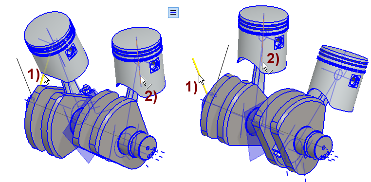
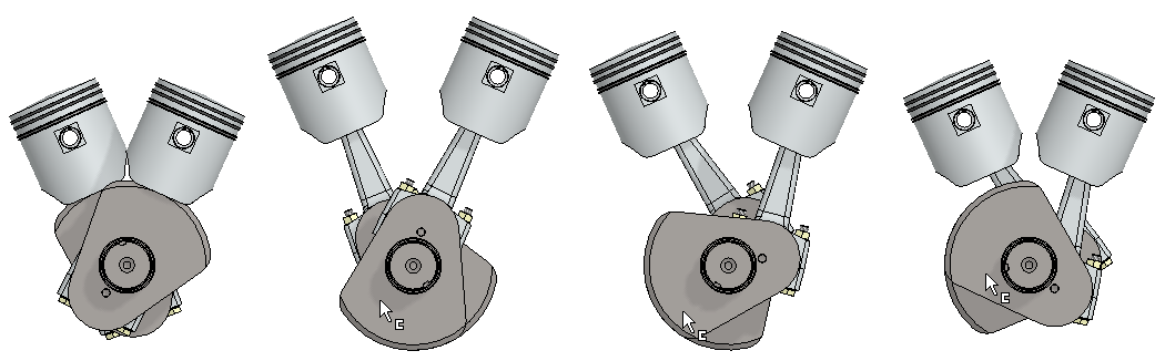
Orient the pistons parallel to the skeleton's oblique lines
-
Add the Parallel constraint between the center axis of the piston and the oblique line of the SKELETON.
-
Do it for both pistons separately as shown in the figure.
Drag (Rotate) the crankshaft
-
The connecting rod-piston assembly rotates so that the pistons maintain their direction, but the position is vague.
-
The position of the pistons can be determined by adding a couple of auxiliary planes to the control curve part (SKELETON) and adding the Coincidence constraint between the end points of the central axis of the piston and the auxiliary plane
Edit Skeleton
-
Click SKELETON part of the feature tree.
-
Right-click function: Hiding > Hide Others.
-
Click SKELETON part of the feature tree.
-
Right-click function: Edit.
-
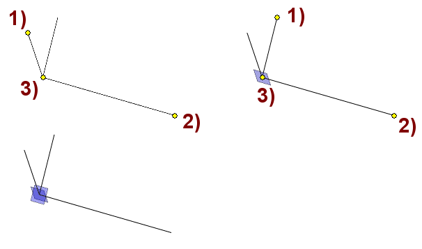
Click three points on the control curve (last point you want the auxiliary level to go to, in the figure 3).
-
Right-click function: New Plane.
-
Add two planes as shown.
These auxiliary planes could have been added to the SKELETON immediately after the guide lines were modeled.
Place the pistons to run on the auxiliary planes
-
Add the Coincident constraint between the auxiliary plane of the SKELETON and the end point of the central axis of the piston.
-
Do it for both pistons separately.
The previously given parallel constraint of the lines of the piston center axis and the control curve lines keeps the pistons in the right direction and the point coincidence at the right plane (in an imaginary cylinder tube).
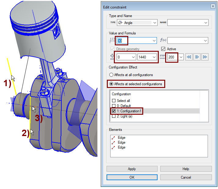
Create a new configuration for the assembly and add an angle constraint to it
-
Click Confuguration (from the feature tree).
-
Right-click function: Add Configuration.
-
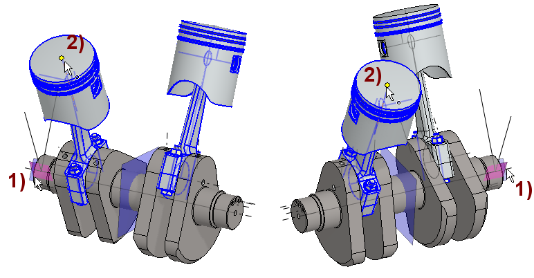
Add the Angle constraintas shown in the figure.
-
Line from the control curve section, in the figure 1).
-
Line from crankshaft, in the figure 2).
-
The line of the axis of rotation from the center line of the crankshaft, in the figure 3).
-
Enter the angle: 90.
-
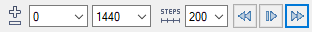
Enter limit values 0 and 1440 and steps in the STEP field: 200.
-
1440 = 4 * 360, ie four full revolutions.
-
-
-
Select that the angle constrain only affects configuration 1.
-
In this case, you can rotate the crankshaft freely in configuration 0.
-
-
The first field has the start value for the simulation.
-
The second field has the end value for the simulation.
-
The STEPS field indicates the number of simulation steps.
-
The more steps, the slower the movement.
-
-

-

-

Simulate motion
-
Above has told how the measure can be simulated in the measure editing mode.
-
You can also simulate the constraint in the feature tree with the right-click function Simulate.
-
Note that in this case the value of the angular constraint remains at one of the two extremes.
-

Save the model
-
File > Save or click
Download the engine model (VX_AS3.vxz) here
-
The names of the configurations in this example model are in Finnish. Detailed= Tarkka, Light= Kevyt.