

Exercise 3: Shelf Support
This exercise was carried out with version 27.0 (Vertex 2021).
In this exercise you will learn to
-
To store a feature and component in a library.
-
Library feature positioning.
-
Adding different radial roundings to the same rounding feature.
-
Creating of a linear pattern.
-
Deleting and restoring an individual feature to a feature pattern.
Functions to be used:
-
Sketching tools, drawing lines and constraints.
-
Operation: Boss - Extrude and Boss - Revolve.
-
Save to Library > As Feature.
-
Pattern.
-
Save to Library > As Component.
-
Library Feature > Boss.
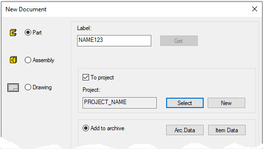
Create a new part
-
File > New > Part.
-
Enter the label (which is also the name of the model and by default will be the name of the drawing).
-
Enter the archive information by clicking Arc.Data.
-
Select the project where the model will be saved.
-
OK.
-
Sketch the pin
-
New Sketch > To horizontal (XY) plane
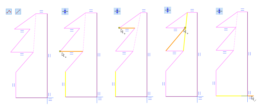
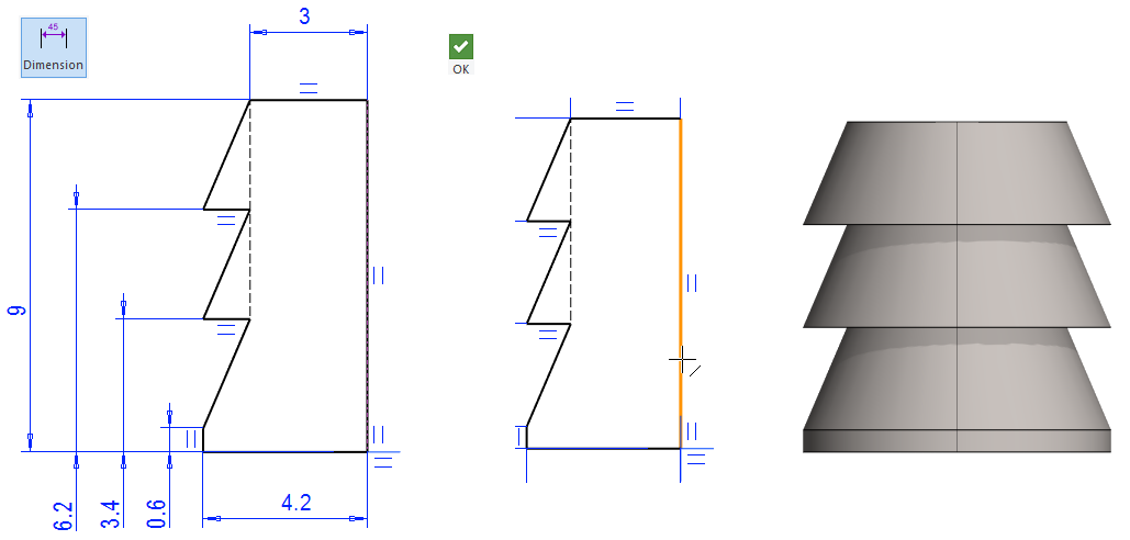
Sketch the shape
-
The functions: Polyline and Two Point Line.
-
Note the vertical and horizontal locks ("equal to" mark in sketch), but do not allow the program to lock at a 45 ° directional angle. If one (direction constraint) accidentally comes up, then remove it. (F9 show or hide constraint symbols)
-
Draw a constraint line from point to point as shown.
-
Add the coincident constraints shown in the figure.
Add the distance constraints
-
See the dimensions in the figure.
-

Operation
-
Boss - Revolve.
-
360 degrees.
-
Click the longest vertical line as the axis of rotation.
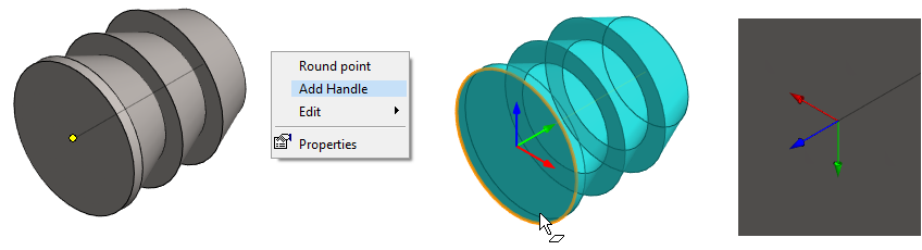
Add Handle
A handle is an element that controls the placement of a feature and component in a geometry.
-
Click the center of the cylinder.
-
Right-click function: Add Handle.
-
Click to the face. The blue axis of the handle turns in the direction: Perpendicular to the face outwards.
-
You can see the handle if you zoom in hard on the point.
-
When the feature containing handle is read from the library and added to the part, then:
-
When you add a substance to a feature (Boss), the blue arrow on the handle points inward from the face.
-
When you remove the feature substance (Cutout), the blue arrow on the handle points outward from the face.
-
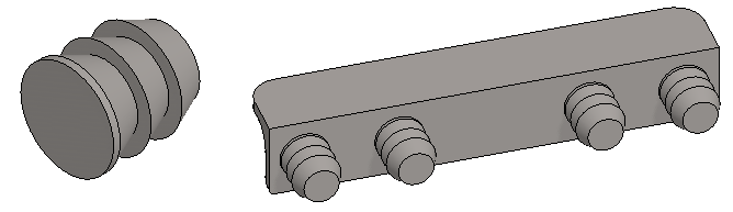
In the figure on the left, the feature was saved to library without a handle, meaning it does not orient to the face.
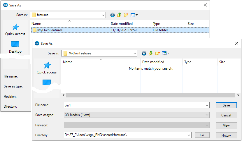
Save the pin to the feature library
-
Right-click function: Save to Library > As Feature.
-
Select a folder or create a new folder under the features folder.
-
Enter the feature a name, eg pin1.
Save the model
-
File > Save or click


Create a new part
-
File > New > Part.
-
Enter the label (which is also the name of the model and by default will be the name of the drawing).
-
Enter the archive information by clicking Arc.Data.
-
Select the project where the model will be saved.
-
OK.
-
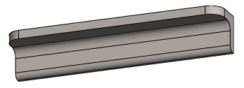
Sketch the body
-
New Sketch > To Vertical (XZ) plane
Sketch the shape
-
The function: Polyline
-
Note the vertical and horizontal lock.
-
Add the Equal Distance constraint (assignments in pairs 1) and 2) and 3) and 4).
-
Add the dimensions, 3 and 13, shown in the figure.
-
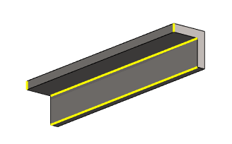
Operation
-
Boss - Extrude.
-
Lenght: 76.
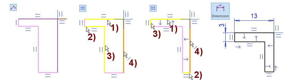
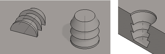
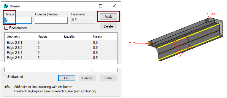
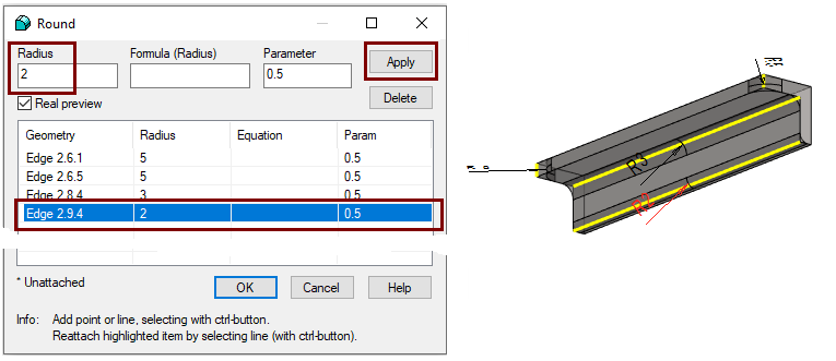
Add roundings to the four edges at once
-
Select four lines according to the figure (Remember the Ctrl key)
-
Enter the most common radius: 5 when all rows are selected.
-
Press the Apply, which saves the radii to all edges.
-
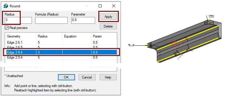
Select the row that defines the rounding of the inside corner.
-
Enter the Radius: 3.
-
Press the Apply to save the radius to this edge.
-
Select the row that specifies the long edge.
-
Enter the Radius: 2.
-
Press the Apply to save the radius to this edge.
-
Since you have entered the radius of all the edges, you can also press directly the OK to complete the rounding of the edges.
-
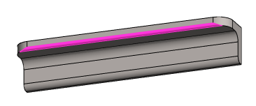
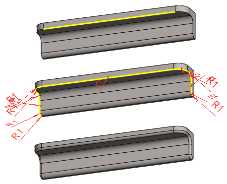
Create a rounding chain
-
Select one edge.
-
Right-click function: Add Round/Bevel > Round.
-
The program shows the members of the chain.
-
Enter the Radius: 1.
-
OK.
The same edge and the function Add Round/Bevel > Single Edge Round are selected below.
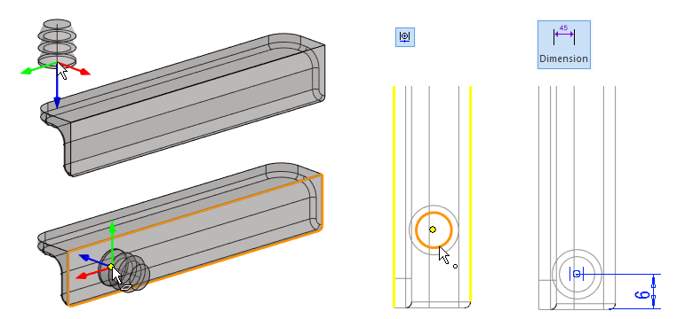
Add a feature stored in the library to the part
-
Right-click function: Library Feature > Boss.
-
Or function Boss (Add Boss using feature from library)

-
-
Right-click function: Refresh Browser. (If the correct folder is not displayed).
-
Find the folder under which you saved the pin.
-
Select a pin, for example, by double-clicking it
-
Or click to a feature and drag it a small distance.
-
-
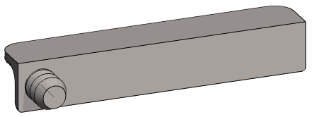
Place the cursor on the right face (the direction of the pin changes) and place the pin on the face.
-
Add a Centering constraint.
-
First click on both the edge lines.
-
Finally, click on the point.
-
-
Add the distance to the end of the part: 6.
-
OK.
Browsers are automatically updated when the Vertex G4 is started.
-
But the browser needs to be updated while working if a feature (or sketch or component) has been saved to the library.
-
A separate update is required because the longer the libraries have grown, the longer it takes to update the browsers, and it does not make sense to update the browsers as soon as the new element is saved.
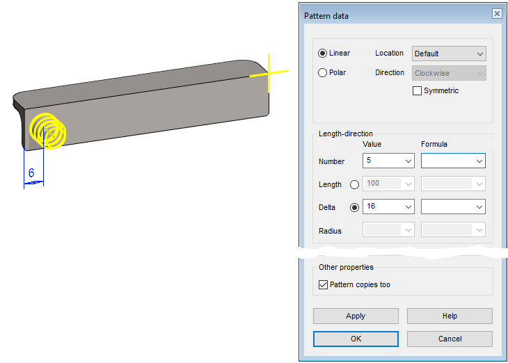
Create a pattern of pins
-
Select a feature from either the feature tree or select a face from the pin.
-
Right-click function: Feature Pattern.
-
Enter feature pattern information:
-
Linear.
-
Number: 5 (Lenght-direction).
-
Delta: 16 (Lenght-direction).
-
OK.
-
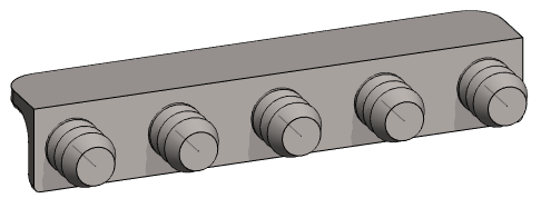
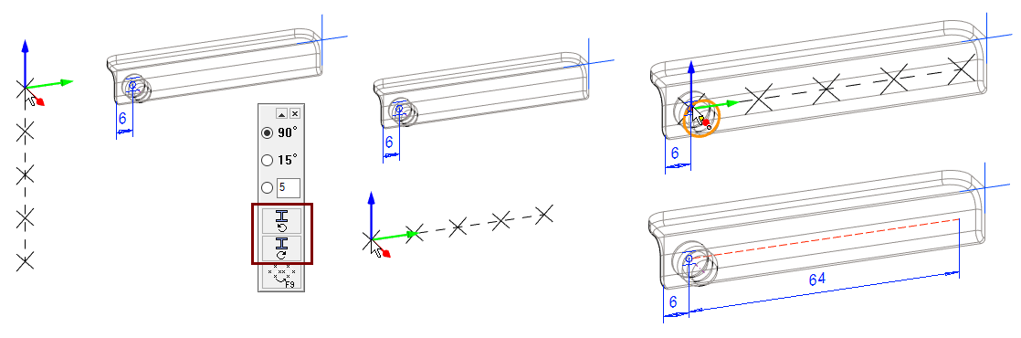
The program progresses to the positioning of the pattern.
-
-
-
If necessary, turn the auxiliary geometry counterclockwise or clockwise.
-
Position the auxiliary geometry so that the cursor is at a position that is reasonable for the feature.
-
OK completes the creation of the pattern.
Remove the middle pin
No middle pin is needed in this pattern, so it will be removed.
-
Select a face from the middle pin.
-
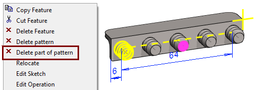
Right-click function: Delete part of pattern.
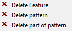
Delete Feature = Deletes the entire pattern and also its first feature.
Delete pattern = Deletes the pattern, but leaves the first feature.
Delete part of pattern = Deletes an individual selected feature.
Restore the members removed from the pattern
You can restore a member of a pattern. You can also delete a member by entering its "address".
-
In the feature tree, select Pattern or select a face from the pattern.
-
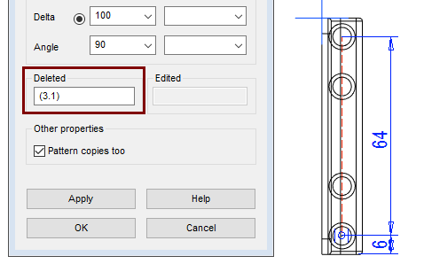
Right-click function: Edit pattern.
-
The Deleted field tells you the address of the feature that was removed from the pattern.
-
The first number is the number of the pattern member from the beginning.
-
The second (after the dot) number is the line number of the pattern. (in this pattern, there are only features in the longitudinal direction, so the line number of all features is 1).
-
-
If necessary, you can clear that address and enter a new address, e.g. (4.1)
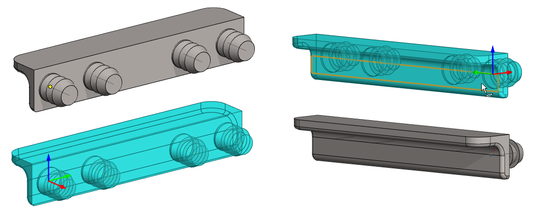
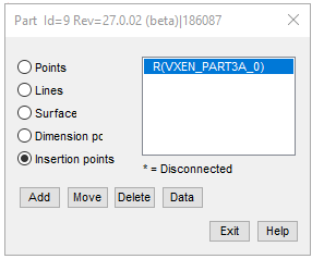
Add Handle
Before saving, add a handle to the part to position the component in other parts.
This shelf support is added to the holes drilled in the sides of the shelf, so place the handle at the center of one of the two end pins at the base of the support body.
-
Click a point. (Look at the picture)
-
Right-click function: Add Handle.
-
Click the face on the opposite side so that the blue axis of handle turns toward it.
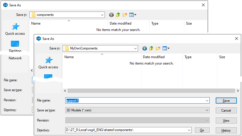
Save the Shelf support to the component library
-
Right-click function: Save to Library > As Component.
-
Select a folder or create a new folder under the components folder.
-
Enter the feature a name, eg. support1.
The features library is used to store the geometry used in the modeling of the part, either as a boss or cutout feature.
The component library is used to store parts that are used in assemblies.
-
Parts are usually purchased and no drawing is required.
-
These are often downloaded online.
Save the model
-
File > Save or click
Further processing of the model (These are presented in Exercise 5 "Drawing on model")
You can add a material item to the model with the right-click function Item Data.
-
These will also appear in the parts list of the model drawing.
You can create a drawing for the model.
-
In the feature tree, select Drawings.
-
Right-click function: New Drawing.
Test the operation of your component
-
File > New > Assembly.
-
Add a part with at least one hole, from the archive.
-
Right-click function: Add > Component.
-
Right-click function: Refresh Browser. (If the correct folder is not displayed).
-
Select a component, for example, by double-clicking it
-
Or click to a component and drag it a small distance.
-
-
Skip dimension table: OK.
-
Position the Shelf Support so that the cursor is over the hole in the other part.
-
If the part does not orient so that the pin faces in through the hole, then there is probably no handle in your part or the handle is in the wrong position.
-
You can edit handles with a Right-click function: Other functions > Edit named elements.
You can also delete a handle by first selecting the point where the handle is attached and using the Right-click function: Delete.