

Exercise 2: Frame with diagonal support
This exercise was carried out with version 27.0 (Vertex 2021) and updatet to version 28.0 (Vertex 2022)
In this exercise you will learn to
-
Drawing the auxiliary geometry of the sketch so that the desired welding gap is left in the corners of the diagonal support perimeter.
-
Adding a profile so that it trims the face.
-
Using the dimension table to vary the dimensions of the profile structure.
Functions to be used:
-
New local part of the assembly.
-
Sketching: Two-point rectangle, Offset line, two point line and dimensioning.
-
Add > Profile.
-
Drawing > New.
-
Dimension table.
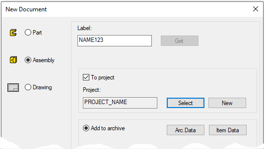
Create a new assembly
-
File > New > Assembly.
-
Enter the label (which is also the name of the model and by default will be the name of the drawing).
-
Enter the archive information by clicking Arc.Data.
-
Select the project where the model will be saved.
-
OK.
-
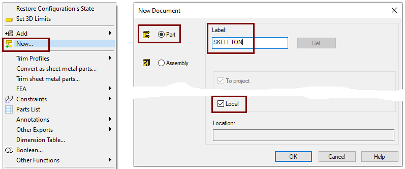
Create a new local part (Skeleton - Guide curve)
-
Right-click function: New > Part
-
Enter a name, eg SKELETON or JIG.
-
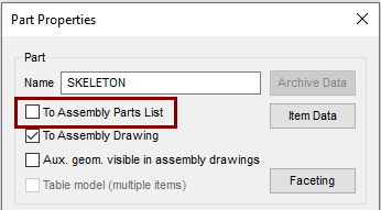
Define that the control curve part does not appear in the parts list
-
Right-click function: Properties
-
Deselect the settings: To Assembly Parts list, because this part is not desired in the parts list, after all it is a completely "intangible" part.
Sketch the skeleton (control curve)
-
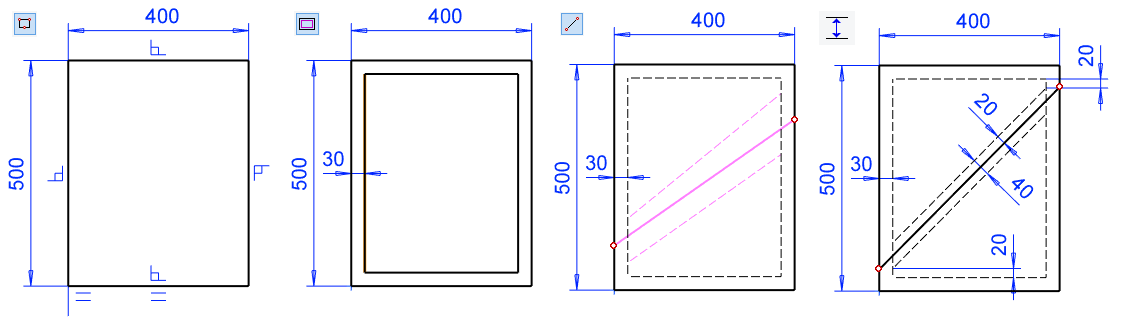
Right-click function: New Sketch > To vertical (XZ) plane.
-
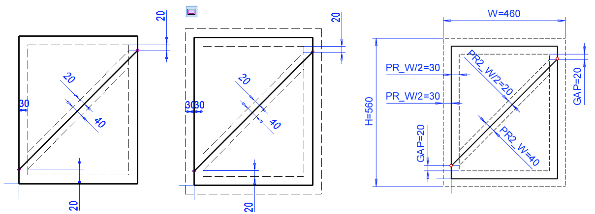
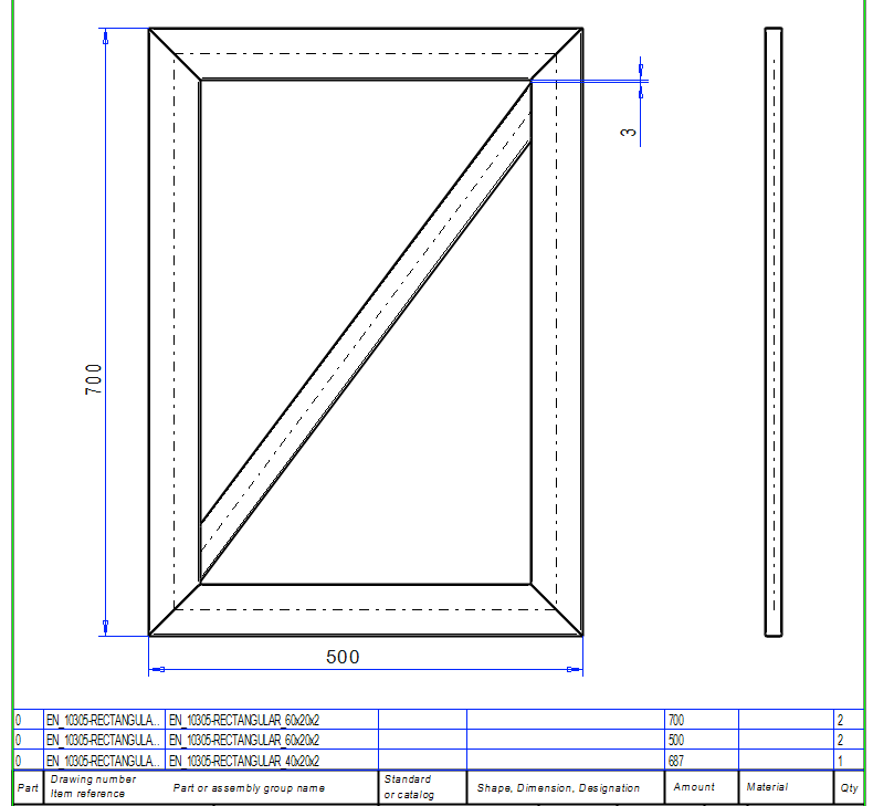
Sketch a rectangle and add dimensions; 500 and 400.
-
Create a parallel copy of the line with the function: Offset. Enter half of the width of the incoming profile, ie 30.
-
Convert offset lines to constraint lines.
-
Sketch the lines according to the third picture. A couple as a construction line and one as a shape line.
-
Add dimensions
-
First dimension 20, from the end of the oblique construction line to the horizontal construction line (picture on the right)
-
Add a distance constraint between the construction line and the shape line: 20.
-
Add a distance constraint between the construction lines: 40.
-
-
OK.
Operation
-
Guode Curve.
Exit from part to assembly
-
OK.
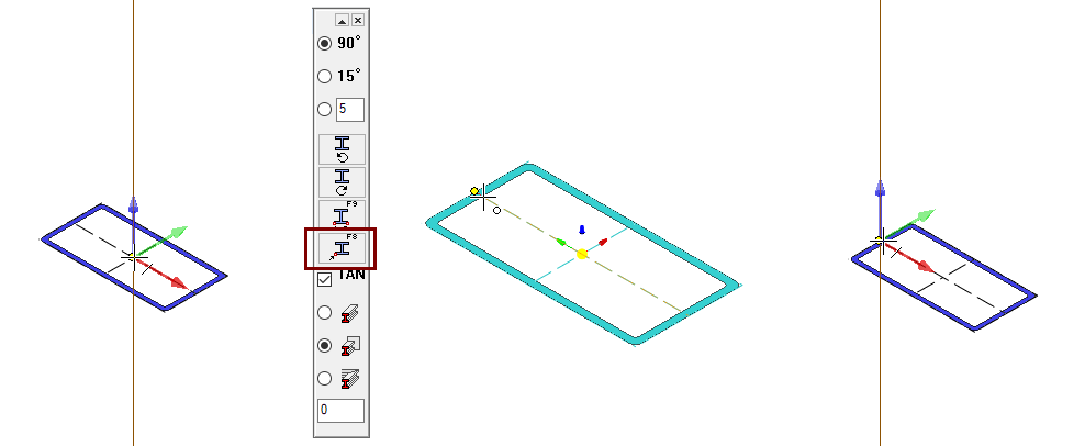
Add outer perimeter profiles
-
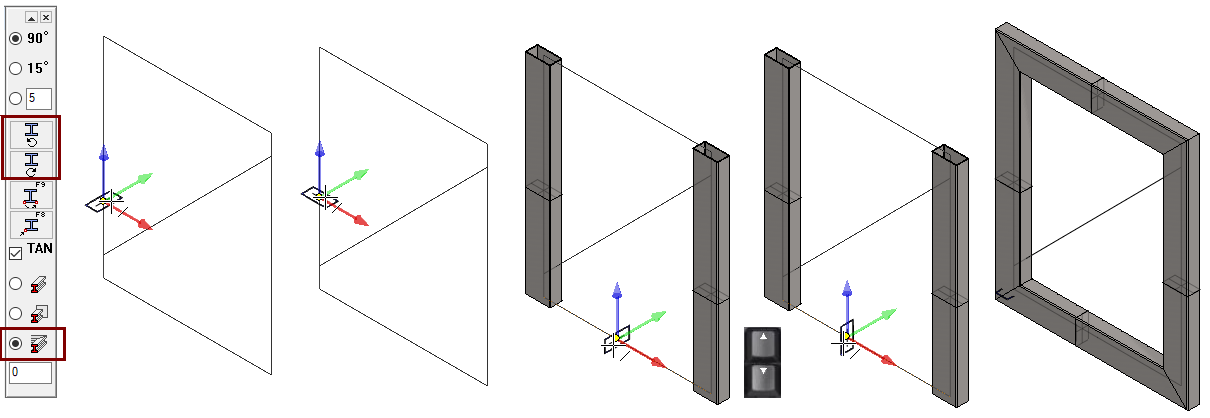
Right-click function: Add > Profile.
-
Select the profile from the library Profiles > Thinwall_tub_spar > SSAB_10305_RECTANGULAR.
-
Select size: EN_10305-RECTANGULAR_60X30X2.
-
Select the trimming mode: Trim automatically to edge.
-
Move the profile over the guide line. If it is in the wrong direction (left image), use the rotate buttons (either counterclockwise or clockwise) in the menu in the upper left corner of the desktop to rotate the profile.
-
You can also use the arrow keys to rotate: The right arrow key rotates the cross-section counterclockwise and the left arrow key rotates the cross-section clockwise.
-
-
Click the guide lines (4 pcs).
-
Press the middle mouse button or press

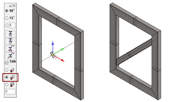
Add diagonal support
-
Select the profile from the library Profiles > Thinwall_tub_spar > SSAB_10305_RECTANGULAR.
-
Select size: EN_10305-RECTANGULAR_40X20X2.
-
Select the trimming mode: Trim automatically to face.
-
Click the guide line.
-
Press

Create a drawing for the assembly
-
In the feature tree, click Drawings.
-
Right-click function: New Drawing.
-
Scale: 1:5
-
Sheet: A3
-
Select projections: front, top and left.
-
Tangential lines: Draw as virtual shape lines (thin).
-
OK progresses to the archive data.
-
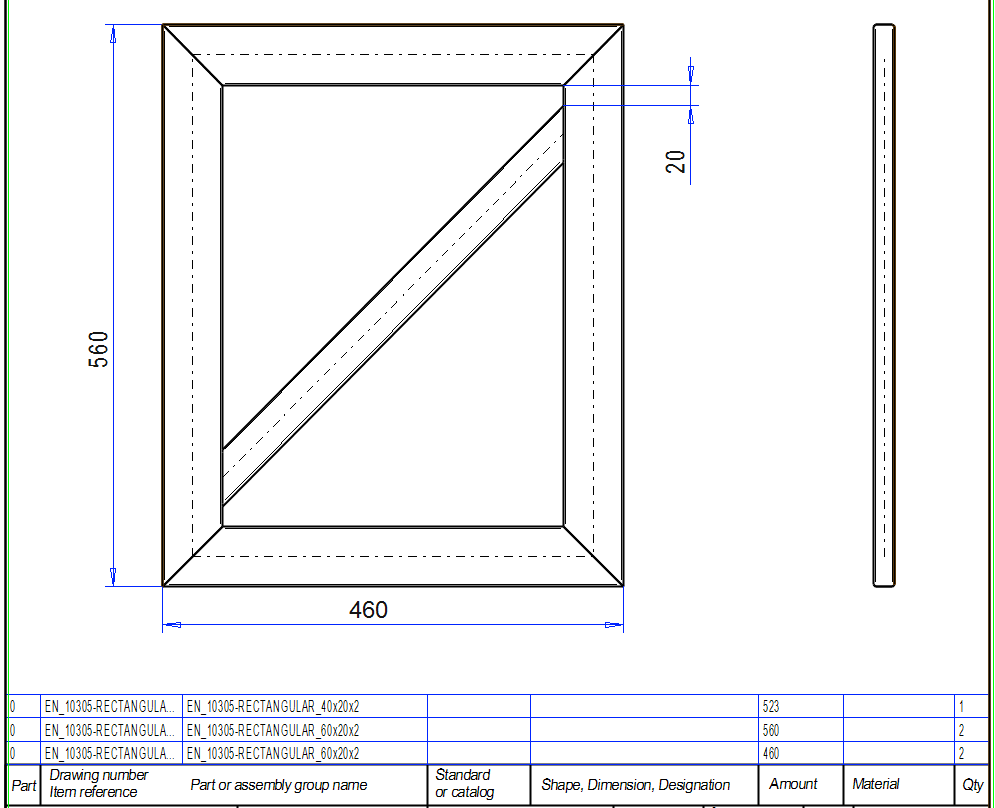
Note that we made a sketch for the dimensions 500 * 400, but that in the model the dimension of the frame becomes 560 * 460.
-
This is because the cross section of the profile is attached to its center at the cursor by default, i.e. the profile extends half the width of the profile outside the guide curve.
Save the drawing and remove it from the desktop
-
File > Save or click


-
Remove the drawing from the cross in the upper right corner.
Save the model
-
File > Save or click
Change the model to dimensionally controlled
Modifications are made to the guide curve part so that the current outer dimensions are removed and construction lines are drawn around the perimeter, given the distance constraints and the dimension variable ID in the formula field.
Edit the guide curve part
First, hide the profiles from the model so that they do not interfere when editing the guide curve sketch of the SKELETON part.
-
Select profiles.
-
second, third, etc. profile
-
the first profile in the feature tree and the last profile wiht the

-
-
Right-click function: Hiding > Hide.
Edit guide curve part SKELETON:
-
Select the model SKELETON from the feature tree.
-
Right-click function: Edit.
-
Click the Guide Curve feature in the feature tree.
-
Right-click function: Edit sketch.
-
Remove the old main dimensions.
-
Create a parallel copy of the line with the function: Offset. Enter half of the width of the incoming profile, ie 30.
-
Convert offset lines to constraint lines.
-
Edit the dimensions of the sketch and enter values in the formula fields:
-
Between frame shape lines and construction lines: PR_W/2. (Profile width / 2).
-
Between the diagonal support and its construction lines: PR2_W/2 and another PR2_W (Be careful that these come logically).
-
For welding gap 20 GAP.
-
-
OK.
Note that the lowercase and uppercase letters are different characters.
We recommend that you use only capital letters in the names of variables.
The variable ID must not begin with a number.
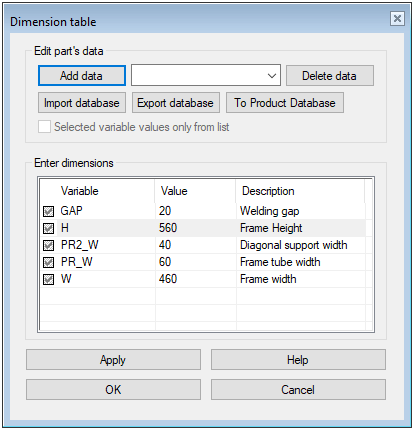
Add descriptions to the Dimension Table
-
Right-click function: Dimension Table.
-
In the row, click the Description column.
-
Enter a description.
-
Do the same for all rows
-
OK.
Exit from part to assembly
-
OK
Restore hidden profiles with right-click function: Restore Hidden, if they are still hidden.
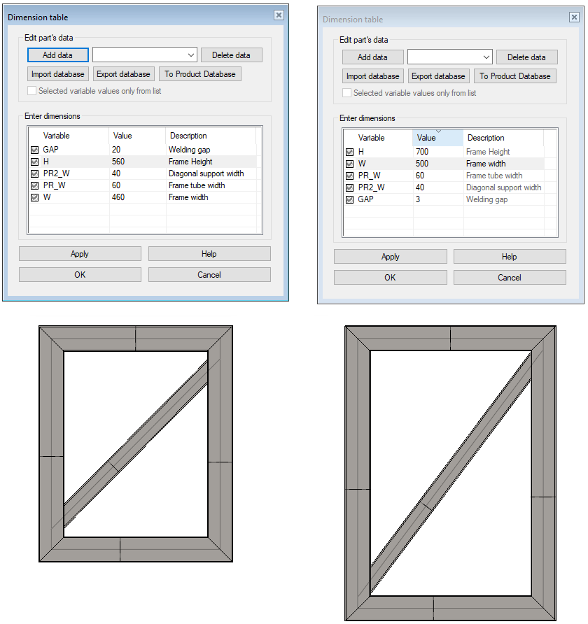
Use the dimension table to edit the dimensions of the model
-
Right-click function: Dimension Table.
-
Enter new values.
-
Note that the values PR_W and PR2_W related to the profile cross-section dimensions should not be changed unless the profile sizes are changed separately.
Note that the size of the frame changes immediately, and the model does not need to be solved separately, as in the first exercise, where the dimension was changed by modifying the control curve part from the sketch.
Click the column heading to arrange the rows in ascending or descending order by column.
Open the drawing of the model
The drawing is updated automatically.
-
Now the H and W dimensions given in the dimension table directly describe the height and width of the frame.
The H and W dimensions of the original guide curve could also have described the dimensions of the frame if the cross-sectional edge of the profile had been placed on the guide line.
-
This is covered in the following exercise
Save the model
-
File > Save or click
Download the model of the diagonal support frame (VX_PROF2vxz) here