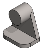
Exercise 2: End bracket
This exercise was carried out with version 27.0 (Vertex 2021).
In this exercise you will learn to
-
Repeat the sketching tools.
-
Extrusion by dimension, in two directions, through the body, to the clicked surface and point.
-
Edit the dimensions of the sketch without going to edit the sketch.
-
Various roundings, including single edge rounding, edge chain rounding and point rounding.
-
Creating and renaming configurations.
-
Hide features (to make the model lighter when it is added into the assembly).
Functions to be used:
-
New Sketch > To auxiliary planes (XY, YZ and XY) and New Sketch > Face.
-
Sketching tools: Adding lines and adding constraints, e.g. Concentricity and Equal Radius constraints.
-
Operation: Boss Extrusion and Cutout Extrusion.
-
Add Round/Bevel > Round, Add Round/Bevel > Single Edge Round and Round point.
-
Configurations > Add Configurations.
-
Configurations > Properties.
-
Hide feature.
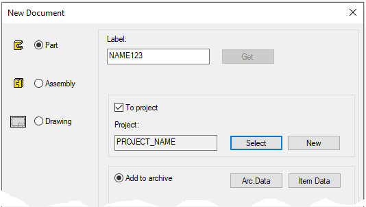
Create a new part
-
File > New > Part.
-
Enter the label (which is also the name of the model and by default will be the name of the drawing).
-
Enter the archive information by clicking Arc.Data.
-
Select the project where the model will be saved.
-
OK.
-
Create the first feature
-
New Sketch > To horizontal (XY) plane
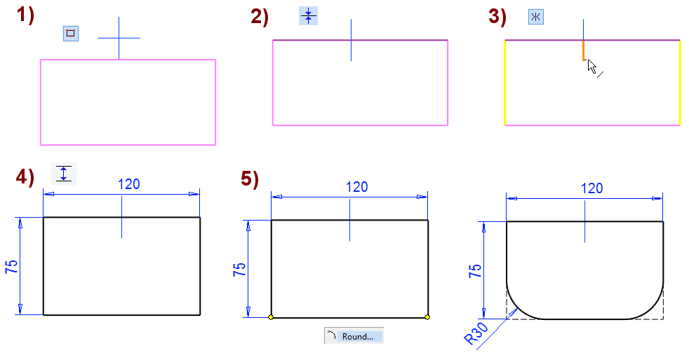
Sketch the shape
-
The function: Rectangle, in the figure 1).
-
Add the coincident constraint between the upper horizontal line and the horizontal line of center cross, shown in the figure 2).
-
In this case, we can use the vertical plane as a sketch plane in later stages.
-
-
Add the symmetry constraint on the vertical lines with respect to the vertical line of the center cross, shown in the figure 3).
-
In this case, we can use the lateral plane when sketch the intermediate support.
-
-
Add the dimension constraints of the base size: 120 * 75, shown in the figure 4).
-

Operation
-
Boss - Extrude.
-
Lenght: 15.
Create the second feature
-
New Sketch > To vertical (XZ) plane
-
Or select the Vertical(XZ) Plane and function New Sketch > Face.
-
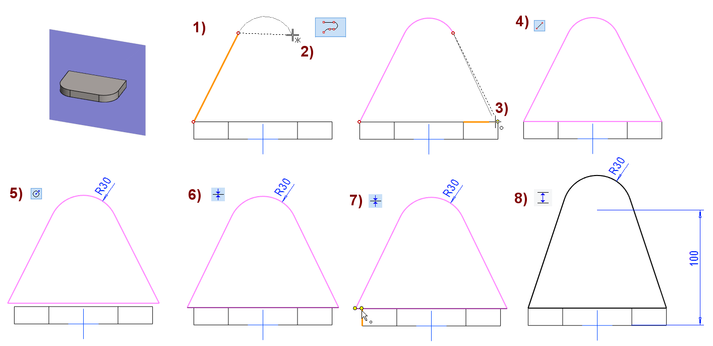
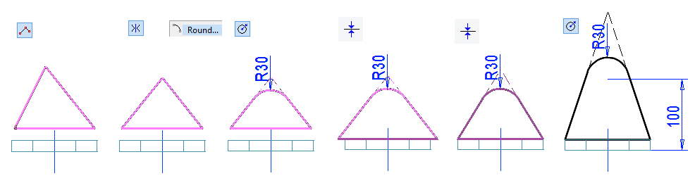
Sketch the shape
-
Use, for example, the Smart line chain, shown in the figure 1).
-
Note the symmetry constraint of cursor when sketching an arc, in the figure 2).
-
Stop drawing the line chain to the point, in the figure 3).
-
-
Complete the cross-section into a closed shape with the function: Two-point line, shown in the figure 4).
-
Add the radius constraint to the arc: 30, shown in the figure 5).
-
The line chain may come off the bottom.
-
The line chain may open, depending on which point the program has interpreted the line segment as the reference point.
-
-
Add the coincident constraints, if needed, shown in the figure 6) and 7).
-
Add the distance constraint from the center of the hole to the bottom: 100, shown in the figure 8).
-
Also make sure that the sketch is defined.
-
All lines in the sketch are black.
-
And you can't drag the lines.
Operation
-
Boss - Extrude.
-
Lenght: 15.
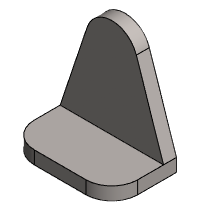
Create the shaft holder
-
New Sketch > To vertical (XZ) plane
-
Or select the Vertical(XZ) Plane and function New Sketch > Face.
-
The extrusion length depends on which plane or face you sketched.
-
Sketch the shape
-
The function: Circle. (Circle with Center and Radii Point).
-
Click the center of the circle to the center point of arc,
-
Select the location of a point on the circumference of the circle,
-
Use a Coincident constraint to make the circle the same size as the arc.
-
Operation
-
Boss - Extrude.
-
Lenght: 60. (if you made the sketch on the inner surface, then 45)

Create intermediate support
-
New Sketch > To lateral (YZ) plane
-
Or select the Lateral(YZ) Plane and function New Sketch > Face.
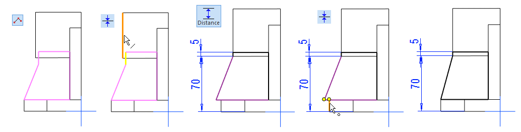
Sketch the shape
-
The function: Polyline.
-
Try dragging the lines.
-
Most lines are likely to drag.
-
-
Add distance and coincident constraints.
-
Distance 70 is accurate.
-
Distance 5 must be large enough so that there is no gap between the extruded support and the cylinder.
-
-
Operation
-
Boss - Extrude - In Both Directions
-
Lenght: 60.
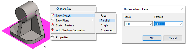
Create the frame of the clamping
-
Restore to the Horizontal(XY) Plane, if it is not already visible.
-
Select the Horizontal(XY) Plane.
-
Right-click function: New Sketch> Parallel.
-
Value: 160.
-
Formula: HEIGHT.
-
The formula allows the height of the clamping slot to be easily adjusted later using a dimension table.
-
Sketch the shape
-
The function: Rectangle.
-
Add a symmetry constraint between the vertical lines and the the vertical line of the center cross.
-
Add distance constraints.
-
Operation
-
Boss - Extrude - To Selected Face
-
Click to the face of the cylinder.
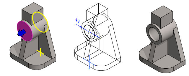
Create the hole for the shaft
-
Select the end face of the cylinder.
-
Right-click function: New Sketch > Face.
Sketch the shape
-
The function: Circle. (Circle with Center and Radii Point).
-
Click the center of circle to the center point of cylinder, so that the concentricity constraint comes with the previous cylinder.
-
Function: Diameter. Enter the value 42.
-
Operation
-
Cutout - Extrude - Thru all.
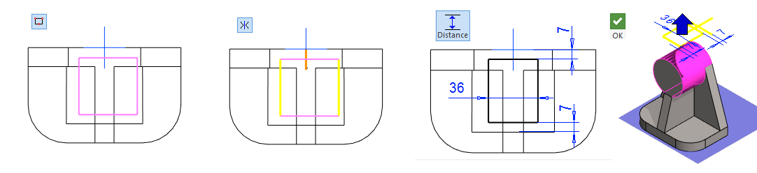
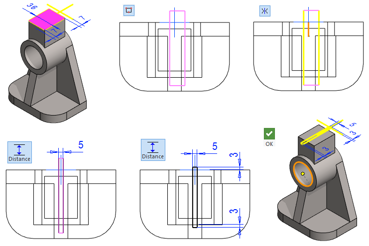
Create the slot
-
Select the top face.
-
Right-click function: New Sketch > Face.
Sketch the shape
-
Sketch the rectangle symmetrically about the vertical axis of the central cross.
-
Add a symmetry constraint between the vertical lines and the the vertical line of the center cross.
-
Add distance constraints.
-
The width of the slot: 5.
-
This constraint would be ok, as long as the sketch of the slot exceeds the length of the cylinder.
-
-
If the part were dimensionally variable, you should add more dimensions to the sketch to ensure that the slot sketch follows the geometry if the length of the cylinder were to increase. The picture shows the dimensions 3.
-
Operation
-
Cutout - Extrude - To Selected Point
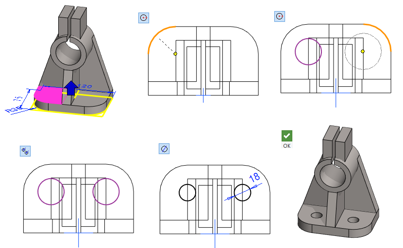
Create the holes in the bottom
-
Select the top of the bottom.
-
Right-click function: New Sketch > Face.
Sketch the shape
-
Sketch two circles.
-
Click the center of circle to the center point of arc so that the concentricity constraint comes with the previous rounding.
-
-
The function: Equal Radius.
-
Click to both circles.
-
Add a diameter constraint: 18.
-
Operation
-
Cutout - Extrude - Thru all.
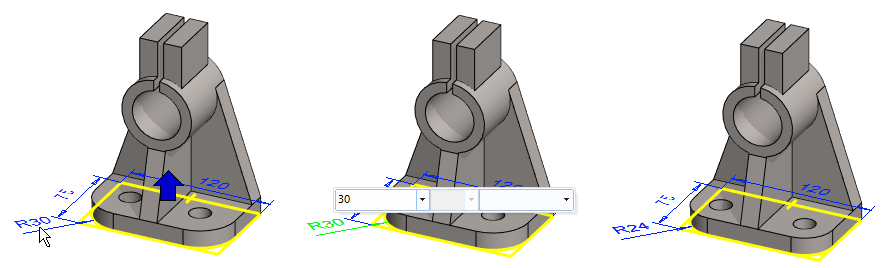
Change the roundings radius of the bottom
At this point, it is observed that the mounting holes of the base should be farther apart.
However, it is assumed that the holes should still be located at the concentricity of the corner roundings.
The bottom was sketched as the first step, so you could go to edit the first sketch, e.g., by double-clicking the first sketch on the history tree.
Use a simple way to edit the dimensions of the sketch.
-
Click once on the first feature of the history tree.
-
The dimensions of the sketch appear.
-
Click once on the measure: R30.
-
Carefully move the cursor to the top right to display the Mini Toolbar (in the middle figure).
-
Click the box that has value 30.
-
Enter the new value: 24.
-
The geometry changes immediately and at the same time the location of the holes in the bottom also changes.
-
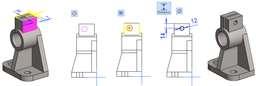
Create slot clamping holes
-
Select the side face of the clamp.
-
Right-click function: New Sketch > Face.
Sketch the shape
-
Sketch a circle.
-
The function: Centering.
-
Click first the vertical lines of the face and then the center of the circle.
-
-
Add a Diameter constraint. Enter the value 12.
-
Add a Distance constraint. Enter the value 14.
-
Operation
-
Cutout - Extrude - Thru all.
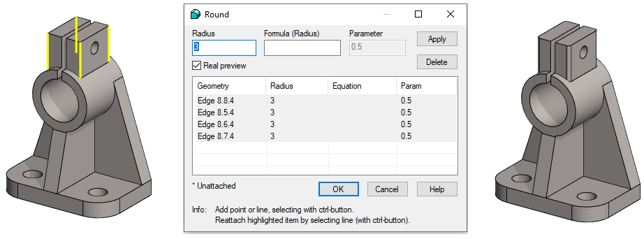
Add roundings for each corner
-
Select individual sharp edges (Remember Ctrl key).
-
Right-click function: Add Round/Bevel > Single Edge Round.
-
Enter the radius: 3.
-
To preview the roundings, press Apply.
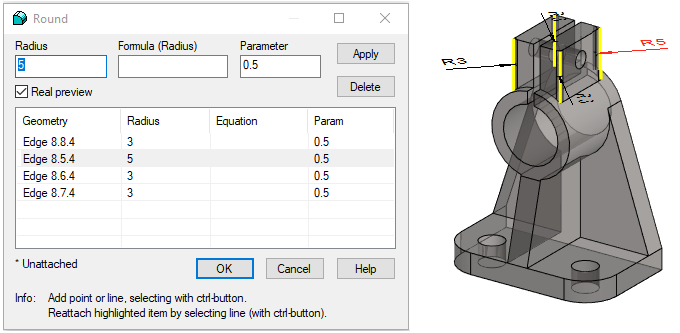
You can add different sizes of rounding to the edges you select.
-
First enter the radius that is most common.
-
Press the Apply.
-
Select the rounding you want to change from either the list or click it in the model.
-
Enter a new value (in the Radius field) and press the Apply.
-
Continue this until you have entered the required radiis.
-
Finally OK.
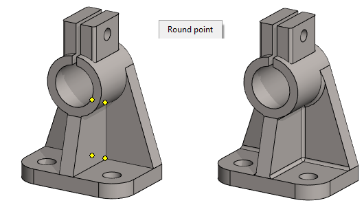
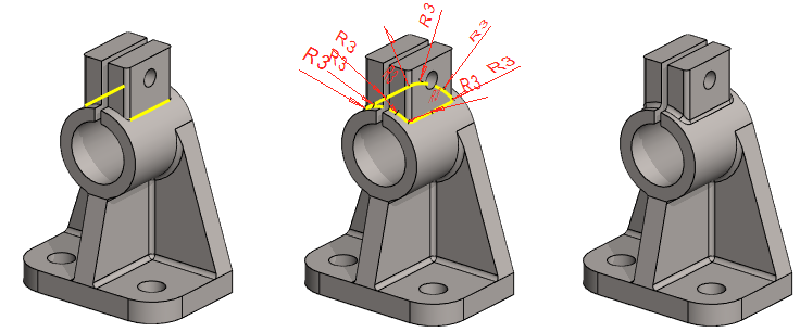
Select points and create roundings
-
Select the 4 points (Shown in the figure).
-
Remember the Ctrl key.
-
You have to rotate the model, so that you can point to the points behind, see Tip *1).
-
Use the middle mouse button to rotate the model. (Ctrl keys must not be pressed in this case).
-
or the Shift key and the right mouse button pressed.
-
-
-
Right-click function: Round Point.
-
Enter the radius: 3.
-
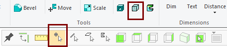
You can click to points that are behind the surfaces, when
-
Select transparency
-
Only Snap to Point is selected in the Tool Strip.
Add a rounding chain
-
Select the 2 lines (Shown in the figure).
-
Right-click function: Add Round/Bevel > Round.
-
Enter the radius: 3.
-
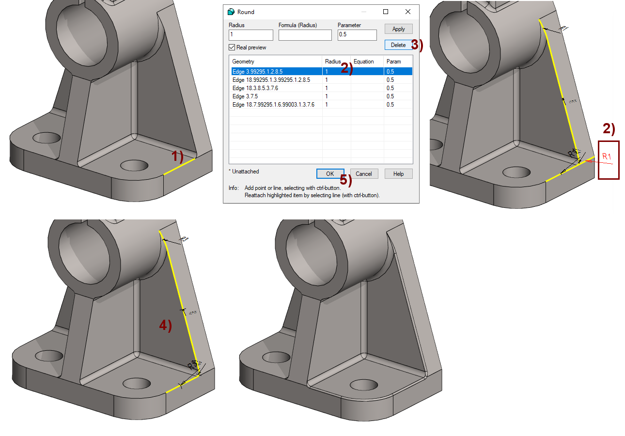
Add rounding to the top of the base (the first side)
It is not possible to create a rounding without additional actions, if the line in the figure 1) is selected and the line chains selected by the program are accepted. The Acis modeler cannot do rounding with these choices, so you need to try different options.
-
If the roundings are small, you should omit them and mention the roundings in the drawing
Add rounding
-
Select one line, figure 1).
-
Right-click function: Add Round/Bevel > Round.
-
Enter the radius: 1.
-
If you now press OK, the program will not make roundings, but will wait for you to edit something in the dialog.
-
-
Select any line, figure 2).
-
or select a dimension from the model.
-
-
Press Delete, in the figure 3).
-
Now the line chain shown in the figure 4) remains.
-
OK, in the figure 5).
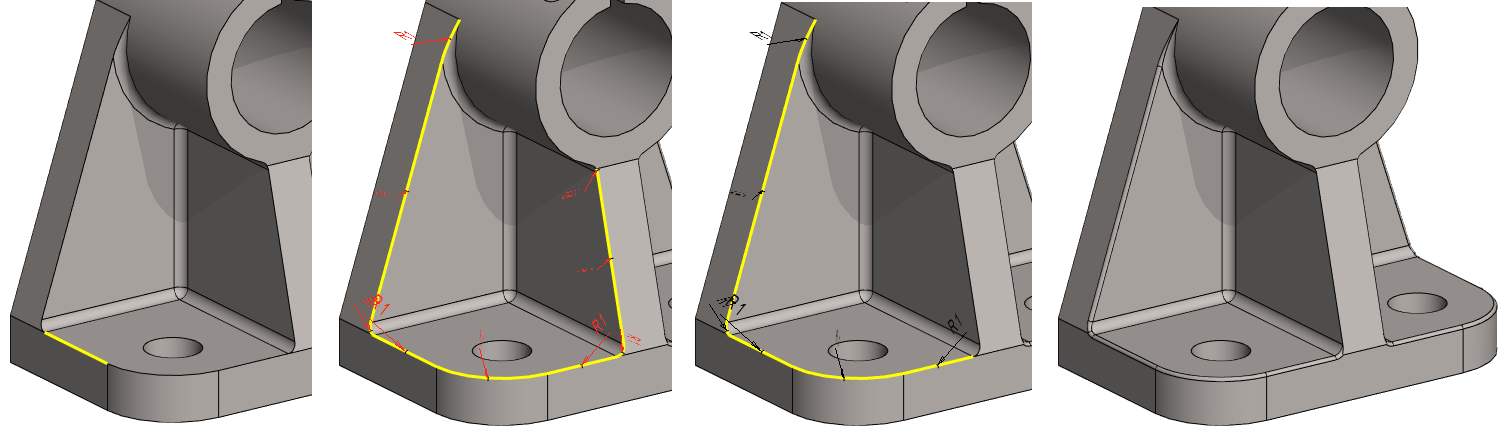
Add rounding to the top of the base (the second side)
When rounding to the other side, the program may find a different line chain to which the rounding cannot be done.
In this case, you have to remove the lines from the selection list as described above and try with OK until the rounding is successful.
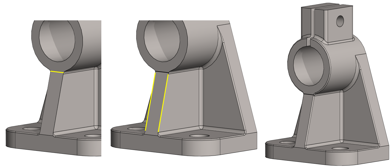
Create front edge roundings
First create a rounding between the end face of the cylinder and the intermediate support. (left figure).
You can then select two lines and round to the chain of lines.
Lightening the model
Rounding brings much more surfaces to the part, so the disk space required by the part increases. When a part is added to an assembly, the number of faces in assenbly also increases.
-
Roundings may be required when making the part or for drawing it.
-
But those roundings of part does not matter at all in an assembly with many other parts.
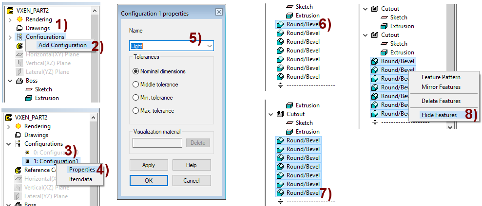
Create a second configuration for the part, from which the roundings are hidden
-
In the feature tree, select Configuration, in the figure 1).
-
Right-click function: Add Configuration, in the figure 2).
-
-
In the feature tree, select: 1: Configuration, in the figure 3).
-
Right-click function: Properties, in the figure 4).
-
-
Change the name of the configuration, for example: Light, in the figure 5).
-
OK.
-
-
Hide all rounding features.
-
Select the first Round/Bevel feature from the feature tree, in the figure 6).
-
Press Shift key and select the last Round/Bevel feature from the feature tree, in the figure 7).
-
Right-click function: Hide features.
-
The part of this exercise takes up disk space (G4 version 27.0.02)
-
275 KB when the roundings are visible.
-
46 KB when the roundings are hided.
This part takes up space when added into the assembly:
-
259 KB when the roundings are visible.
-
32 KB when the roundings are hided.
All roundings (which you have not done in the sketch) should not be done before the other geometry of the part has been completed.
You should not add any roundings (skectch roundings can be used) before all geometry of the part is comleted.
-
The editing of features during modeling is faster when the program does not have to regenerate roundings between other features.
-
In addition it is easier to make the model a lighter when all the roundings are at the end of the history tree.
Save the model
-
File > Save or click


Further processing of the model (These are presented in Exercise 5 "Drawing on model")
You can add a material item to the model with the right-click function Item Data.
-
These will also appear in the parts list of the model drawing.
You can create a drawing for the model.
-
In the feature tree, select Drawings.
-
Right-click function: New Drawing.
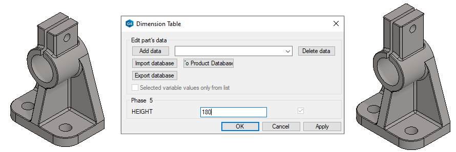
Try varying the model using a dimension table
-
Right-click function: Dimension Table.
-
Enter a new value for HEIGHT, e.g. 180.
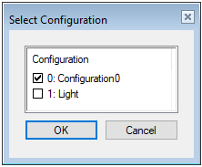
When such a model with multiple configurations is imported into the assembly, the program will ask you to select the desired configuration.
-
In most cases, you should choose a light configuration.