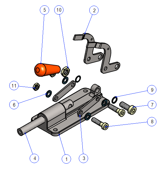
Exercise 2: Destaco clamp
This exercise was carried out with version 27.0 (Vertex 2021).
In this exercise you will learn to
-
To import a Vertex-compressed project.
-
To add parts (models and library components) to the assembly.
-
To locate parts with each other using constraints.
-
To measure distances and diameters of cylindrical faces in a model.
-
To locate components using geometries already in the model.
-
To create a drawing for model and lightweight assemply for other assemblies.
-
To control the hiding of parts with configurations.
Functions to be used:
-
Add > Model. Add > Component.
-
Constraints: Concentricity, Coincidence, Parallel.
-
Distance > Distance and Radious/Diameter.
-
Configurations > Add Configuration, Properties.
-
Hiding > Hiding at configurations.
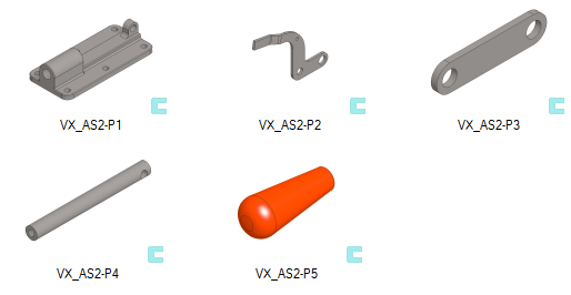
Get a project that includes the necessary parts
-
Download the zipped Vertex project (VX_AS2_PARTS.vxz) here.
-
Drag the file from the downloads section of your Internet browser onto Vertex G4.
-
Be sure the models are found (in browser B) in project VX_COURSE_ASSY.
-
If necessary, refresh your browser, if those models VX_AS2-P * are not found immediately.
-
Vertex model and project chips are identified by the vxz file extension. Such a * .vxz may include an individual part model and its drawing, or an assembly model and its drawing or, for example, all models of the assembly and their drawings, or alternatively an entire project with its models and drawings.
You can import them instead of dragging
-
File > Open File.
-
Archives ribbon > Project group > Import.
-
You can also drag multiple Vertex zips from the directory to your Vertex desktop.
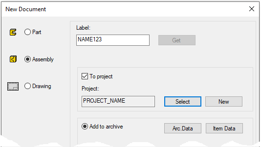
Create a new assembly
-
File > New > Assembly.
-
Enter the label (which is also the name of the model and by default will be the name of the drawing).
-
Enter the archive information by clicking Arc.Data.
-
Select the project where the model will be saved.
-
OK.
-
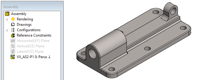
Add a frame
-
Add a part VX_AS2-P1 to the origo of the assembly. (from project VX_COURCE_ASSY).
-
Right-click function: Add > Model.
-
or

-
-
Drop the part into place with


You should use the dight-click function Add > Model (or Add> Component) function if you are adding several different models to a configuration, because after placing a part, the OK or V key returns to the (insert) browser, where you can double-click to select a moldel without interruption.
After the part added using the
-
If you have locked the B browser open, for example on the adjacent screen, you can quickly drag the next part to the assembly after selecting OK or the V key.
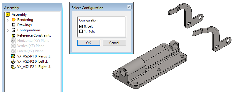
Add both halves of the lever to the model
-
Right-click function: Add > Model.
-
Double-click the part VX_AS2-P2.
-
First select the configuration: 0: Left.
-
Point to a place (from the air).
-
-
Double-click the part VX_AS2-P2 again.
-
Select the configuration: 1: Right.
-
Point to a place (from the air).
-
Press

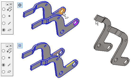
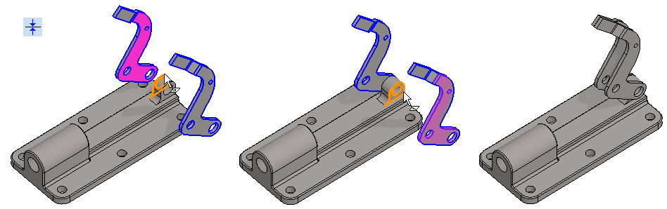
Position the lever halves together
-
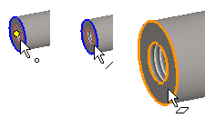
Add a concentricity constraint to the holes.
-
Faces are easier to choose if Snap to face is selected in the auxiliary menu.
-
-
Add a parallel constraint to the lines.
-
Lines are easier to choose if Snap to line is selected in the auxiliary menu.
-
You can also put a parallel constraint on two faces (but it is simpler for the constraint solver to put the lines parallel).
-
Drag the lever
-
The levers turn at the same pace, but the distance between them slides.
Position the lever halves on the frame
-
Click the other half of the lever (VX_AS2-P2).
-
Select: Add concentrity constraint.
-
Click the cylinder face at the selected part. In the figure.
-
Click on the frame part (VX_AS2-P1).
-
Click on the cylinder face on the frame.
-
If the levers cover the faces required in the next section, you can drag the levers before giving the following constraint.
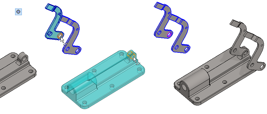
Add the Coincidence constraint between frame and levers.
-
Coincidence constraint.
-
Click to the face of the lever (or frame).
-
Click to the face of the frame (or lever).
-
Repeat for both halves of the lever.
-
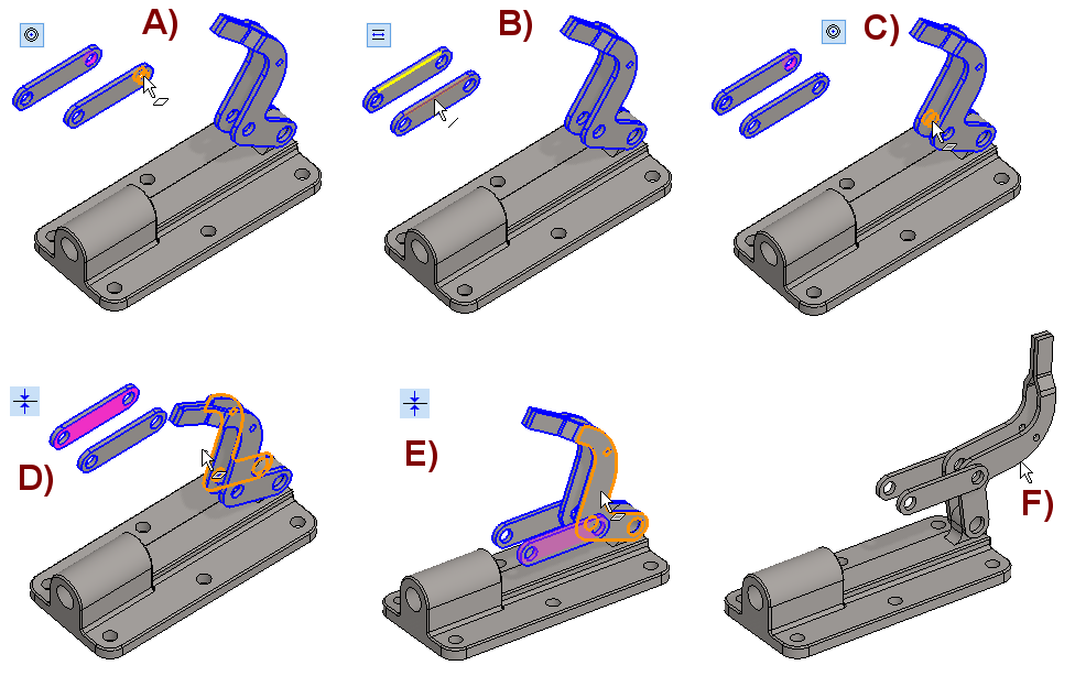
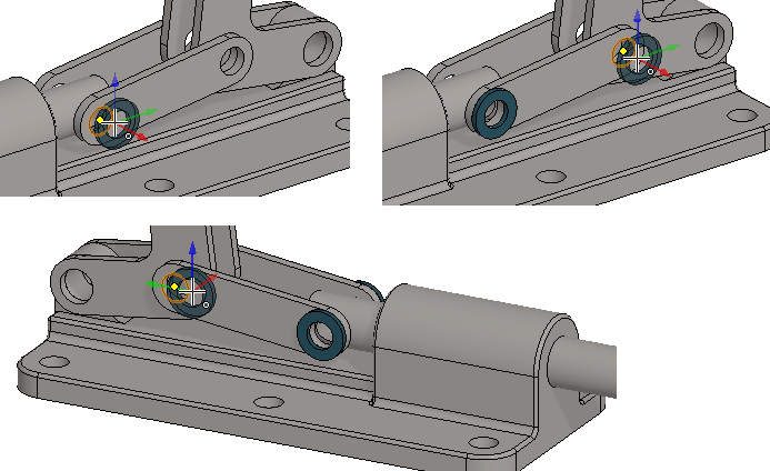
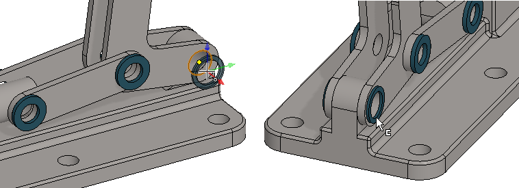
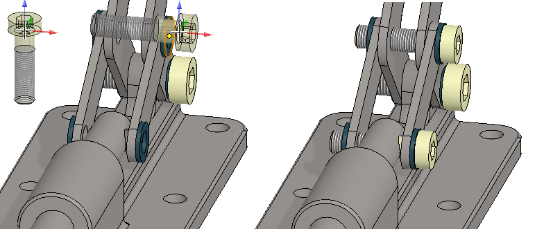
Add two loops and position them
-
Add the loop (VX_AS2-P3) twice.
-
Add the concentricity and parallel constraints between the loops, in the figure A) and B).
-
Add the concentricity constraint between the lever and the loop eye, in the figure C).
-
Add the Coincidence constraint between the inner faces of the loops and the outer faces of the levers, in the figures D) and E).
-
Drag the lever, in the figure F).
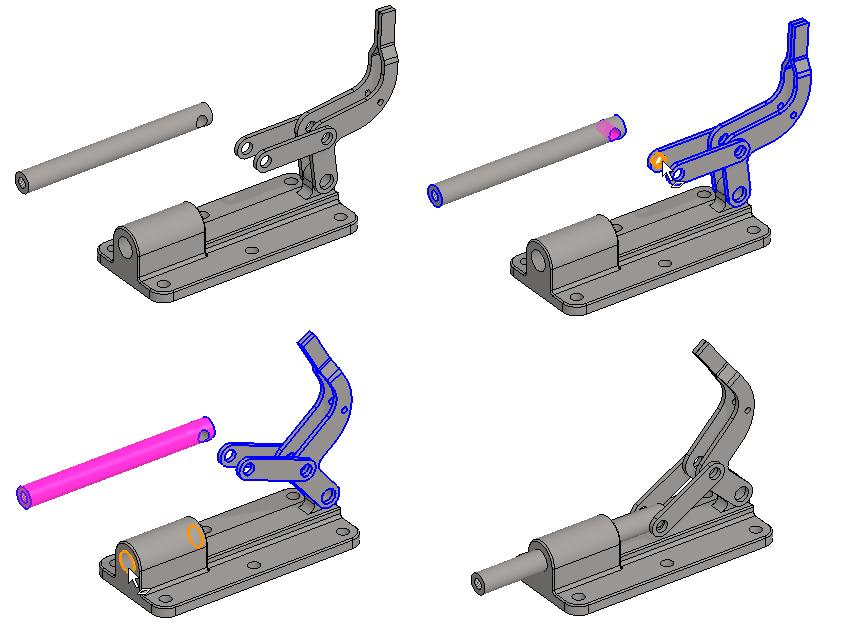
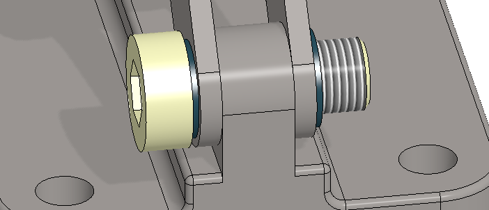
Add rod and position it
-
Add the rod (VX_AS2-P4)
-
Add the Concentricity constraint between the hole in the rod and the loop.
-
Add the Concentricity constraint between the rod and the frame.
-
Drag the lever.
If you want to see the actual trajectory, turn on dynamic collision view:
-
Function: Dynamic (From the Assembly ribbon, in Collision Detection group).
-
Drag the lever.
-
It may be that the lever freezes to some position that indicates a collision, and dragging will not be successful until you take the dynamic collision detection off.
-
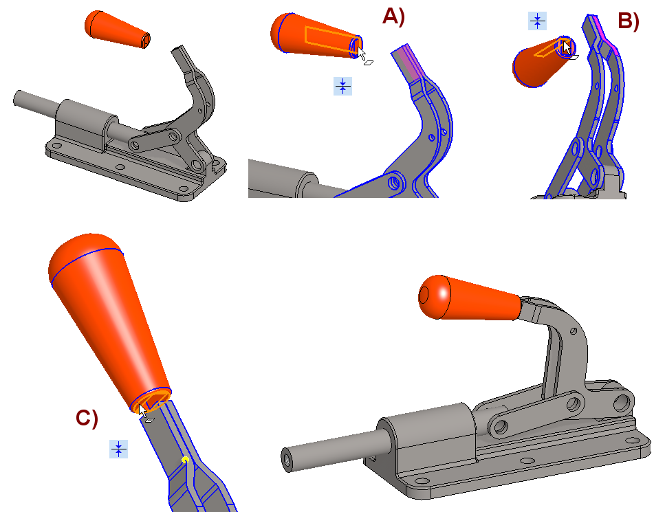
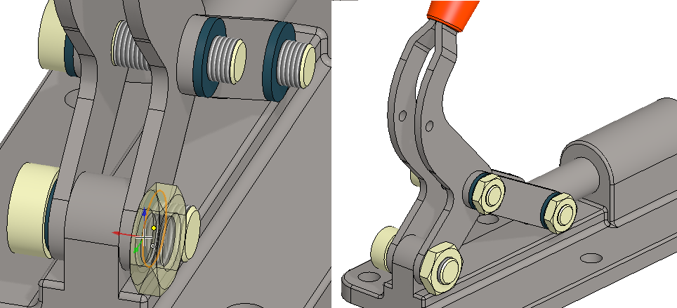
Add and position the lever handle
-
Add the handle (VX_AS2-P5)
-
Add two Coincidence constraints between the handle and lever faces, in the figures A) and B).
-
Add the Coincidence constraint between the bottom surface of the handle and the point of the lever, in the figure C).
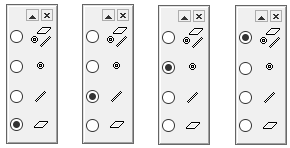
The three auxiliary functions on the left, exclude other elements, i.e. the cursor only snap faces, lines or points.
The rightmost Snap to all entities finds all element types.
-
If the cursor search area has a point and other elements, a point is selected.
-
If the cursor search area has a line and a face, a line is selected.
-
If there is only a face in the cursor search area, it is selected.
If you only want to use the Snap to all entities auxiliary option, you should zoom the model as needed so that only the desired element type hits below the cursor.
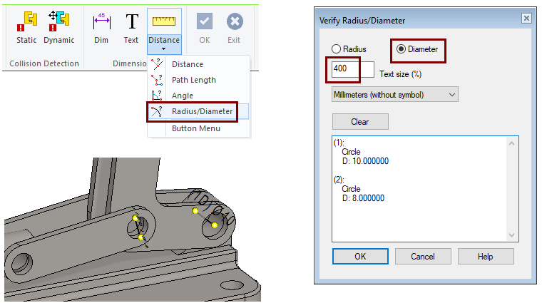
Measure the diameter of the holes so that you can add the correct size components
-
Function (in the ribbon): Distance > Radius/Diameter.
-
Select: Diameter.
-
Click to cylinder surfaces or circle/arc lines.
-
The program lists the cylinders and circles in the dialog and also draws the dimension in the model.
-
-
Use the Text Size (%) field in the dialog to increase or decrease the dimensions displayed in the model. Rotate the model as needed to make the dimensions more visible.
-
Dimensions disappear from the model when you exit the dialog.
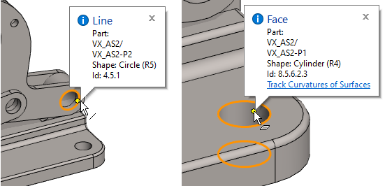
When the Distance function in the Distance menu is running, a cursor hovered over a surface or line reports the element type and the radius of the arc or cylinder in the tip text.
Add four washers from the component library to the loops.
-
Use the right-click function Add > Component (or the B browser or the Add function on the ribbon).
-
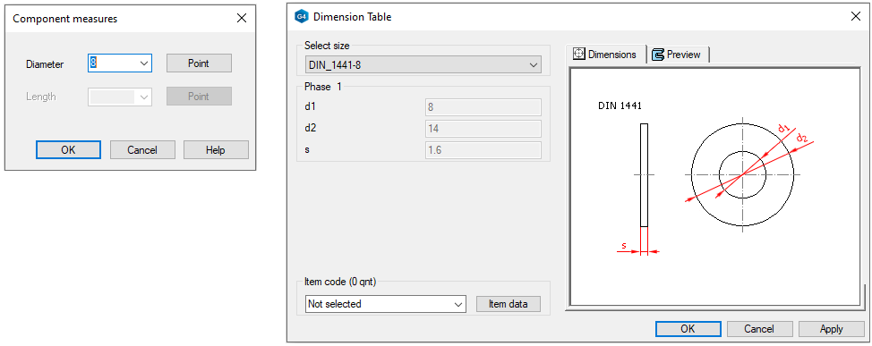
Choose a component from the library: (Libraries > Components > Standard >) Fasteners> Washers > DIN_1441.
-
In the Component measures dialog box, select Diameter: 8 and press OK.
-
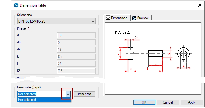
Click OK to skip the item selection in the Dimension Table dialog.
-
Add it to the four positions, before pointing out the location, note that the cursor reports hitting the correct point, which also positions the component correctly.
-
Add two washers from the component library to the levers
-
Select the component Washers > DIN_7603-A.
-
Select the diameter: 10.
-
Place the two components.
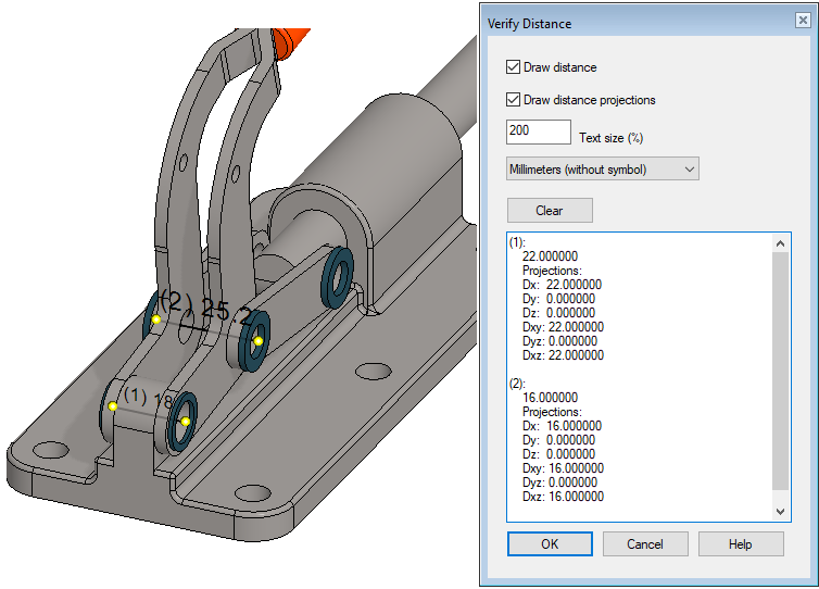
Measure the distances for the length of the screws to be added.
-
Function (in the ribbon): Distance > Distance.
-
Click to the points on the outer surfaces of the washers.
Add screws
-
Use the right-click function Add > Component (or the B browser or the Add function on the ribbon).
-
Choose from the Library (Libraries> Components > Standard >) Fasteners > Screws > Standard thread > DIN_6912.
-
Select Diameter: 10 and Length: 25. OK.
-
If you have genuine items from your own company that would be linked to the component dimension data, you could select an (storage) item.
-
Click it to a place.
-
Add the same screw, but in a different size twice
-
Choose from the Library (Libraries> Components > Standard >) Fasteners > Screws > Standard thread > DIN_6912.
-
Select Diameter: 8 and Length: 30. OK.
-
If necessary, select the (storage) item.
-
Click them to a places.
Add nuts
-
Use the right-click function Add > Component (or the B browser or the Add function on the ribbon).
-
Choose from the Library (Libraries> Components > Standard >) Fasteners > Nuts > Regular_Thread > DIN_EN_24035-B.
-
Add size 10 once and size 8 twice.
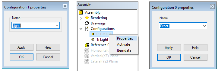
Create a new confuguration for the model and rename the confugurations.
-
Click Confuguration (from the feature tree).
-
Right-click function: Add Configuration.
-
Enter the name of the configuration: Light.
-
Click the first confuguration 0: Default and right-click function: Properties.
-
Rename it: Exact.
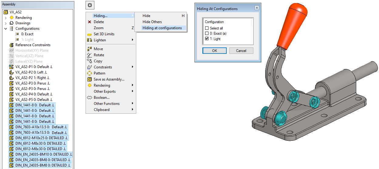
Hide screws and washers from a light confuguration
-
Select all components from the feature tree.
-
Click the first component in the list.
-
Press the

-
-
Right-click function: Hiding > Hiding at configurations.
-
Select the confuguration: 1: Light.
-
(a) indicates the user the currently active confuguration.
-
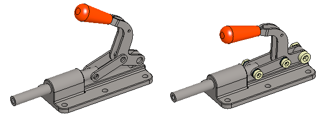
Test hides by changing confugurations.
-
In the feature tree, double-click the confugurations:
-
0: Exact.
-
1: Light.
-
Save the model
-
File > Save or click


When you add model like that to your assembly
-
Add the confuguration: 1: Light, as screws, nuts, and washers only unnecessarily increase the number of elements to be processed in the assembly, and those have little value to the assembly.