

Exercise 14: Casting molds
This exercise was carried out with version 27.0 (Vertex 2021).
In this exercise you will learn to
-
Modeling a plane spiral.
-
Using a sketch feature to model a cross section.
-
Modeling rounding chains when edges are added to the chain.
-
Making variable radius rounding.
Functions to be used:
-
Sketching: Circle, arc with three points, two-point line and polyline.
-
Sketching: Diameter, radius, distance, dimension and tangential constraints.
-
Sketching: Round
-
Operation: Cross Section, guide curve, extrude, revolve and sweep.
-
Spiral (On a plane).
-
Add Round/Bevel > Round.
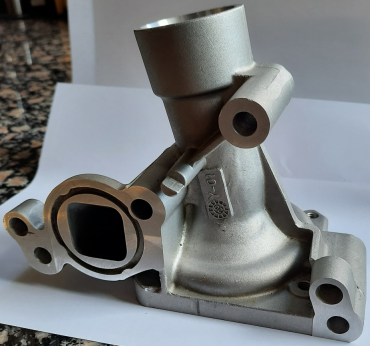
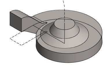
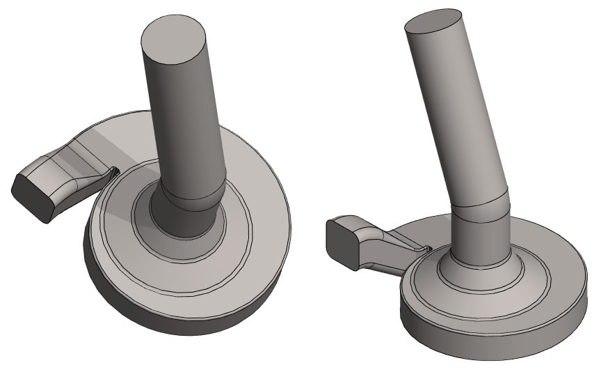
This exercise follows the modeling of the inside of a casting (water pump) like the one below. But the shape and dimensions have been invented.
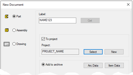
Create a new part
-
File > New > Part.
-
Enter the label (which is also the name of the model and by default will be the name of the drawing).
-
Enter the archive information by clicking Arc.Data.
-
Select the project where the model will be saved.
-
OK.
-
Model a circular cross section
-
Right-click function: New Sketch > To horizontal (XY) plane.
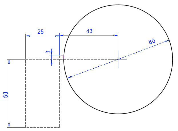
Sketch the shape
-
Draw a circle. Use a Shape line style.
-
Point to the center of the origin of the sketch.
-
-
Draw other geometry. Use the Guide line style.
-
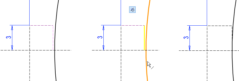
Add Dimension Constraints (or Diameter and Distance Constraints) as shown.
-
Add a tangential constraint between a short vertical line and a circle.
Operation
-
Cross Section.
If the program does not allow a cross-sectional operation, then perhaps some of the line is drawn with a shape line.
-
Turn them into guide lines.
If, after the operation, the desktop appears empty, the reason is that the auxiliary geometry is hidden.
-
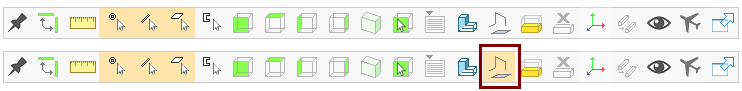
To display the auxiliary geometry, press G or use the toolbar's Show Reference seometry function.
Model the spiral
-
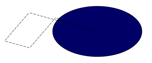
Click the cross section.
-
Right-click function: Add Spiral.
-
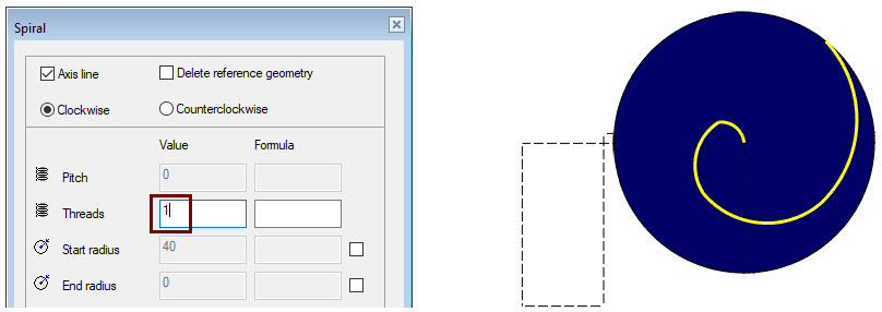
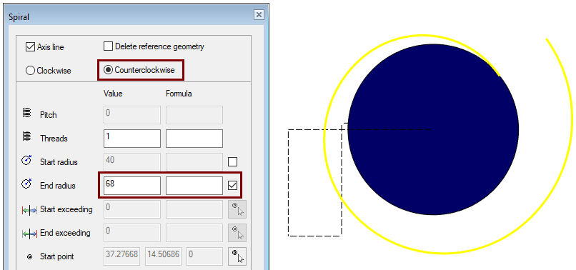
The program opens the dialog Spiral.
-
-
Enter the number of threads: 1.
The program uses the radius of the circular cross section as the radius of the beginning, and sets the radius of the end to zero, i.e. the center of the circle.
-
If the direction of the spiral is Clockwise, change the direction to Counterclockwise.
-
Select End radius.
-
Enter the end radius: 68.
-
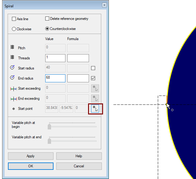
Point to the location of the starting point of the spiral at the lower end of the short vertical guide line. (Look at the picture).
-
OK creates a spiral.
Model the base
-
Right-click function: New Sketch > To horizontal (XY) plane.
Sketch the shape
-
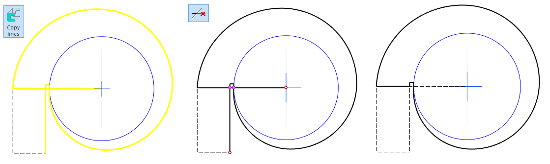
Copy lines to the sketch plane.
-
Function: Copy lines or
-
Right-click function: Line > Copy to Sketch Plane.
-
-
Select the Guide line style.
-
Click the lines you want to copy.
-
Give the Ready command with:
-


-
-
Use the Delete Section function to remove extra parts of the lines.
Operation
-
Boss > Extrude: 17.
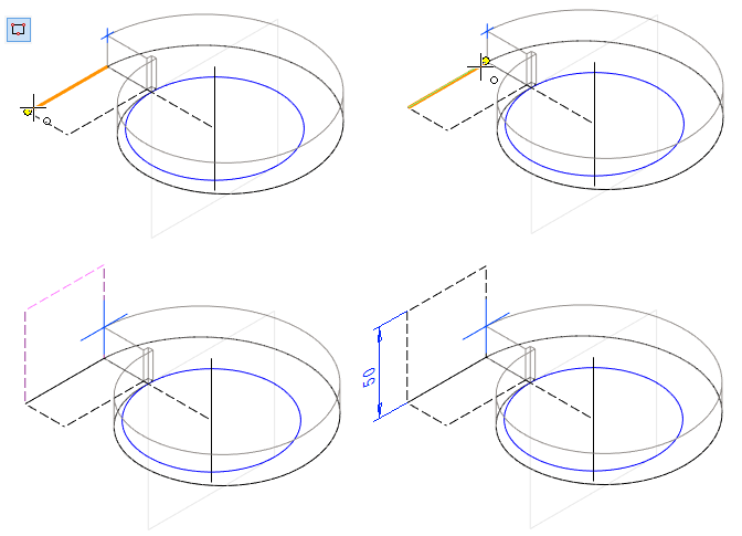
Make a new sketch using the auxiliary plane and point
-
Return the Lateral (YZ) plane if it is hidden.
-
Select the hidden auxiliary plane: Lateral (YZ) plane.
-
Right-click function: Restore.
-
-
If necessary, change the size of the auxiliary plane.
-
Click the auxiliary plane.
-
Right-click function: Change Size. (Ex. 80).
-
-
Select the auxiliary plane and the corner point (shown in the figure) (Remember the

-
Right-click function: New Sketc.
If you have the sketch option Perpendicular selected, the program will turn the part upside down.
-
In that case, select Isometric View from the tool strip.
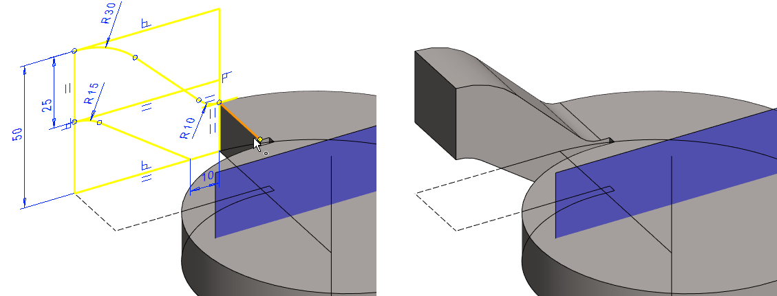
Model the cam
Sketch the shape
-
Sketch and dimension a rectangle.
-
Select the Contruction line style.
-
Click to the first two points of the control curve endpoints.
-
Add dimension constraint: 50.
-
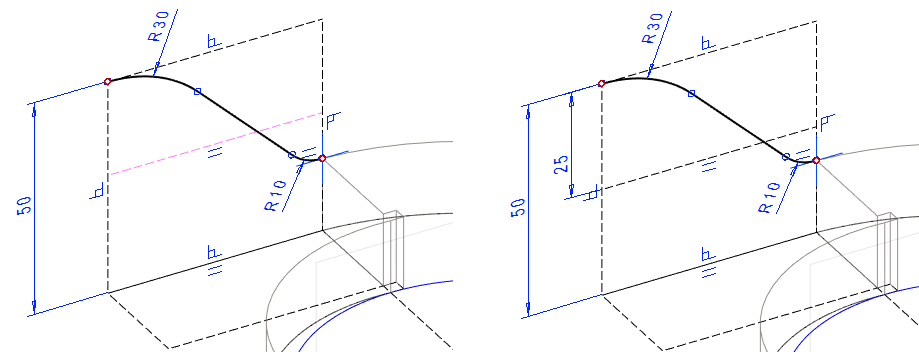
Sketch two tangential arcs with the function: Arc with three points.
-
Click the starting point of the arc so that the upper horizontal line with the point is colored with attention color. (You get tangentiality to the arc).
-
Click the starting point of the second arc so that the horizontal line of the origo and the point is colored with attention color.
-
-
Skecth a Two-Point line between the endpoints of the arcs.
-
Add a tangential constraints between the line and the arcs.
-
Add radius constraints.
-
Lower arc: 10.
-
Upper arc:: 30.
-
-
Sketch and dimension the horizontal construction line.
-
Distance to the top: 25.
-
-
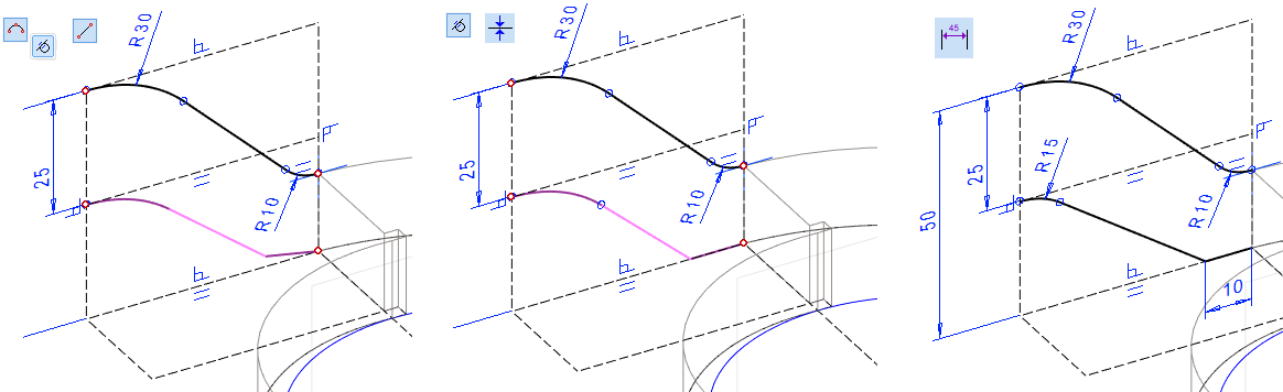
Sketch the shape of the lower surface of the cam using an arc with tree points and a two-point line.
-
Select the Shape line style.
-
-
Add a tangential constraints between the line and the arcs.
-
Add a
coincident constraint
between the lower period of polyline and the guide line.
-
Add the radius constraint of the arc (15) and the distance constraint of the lower line (10).
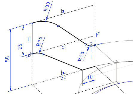
Close the shape by adding two vertical two-point lines.
-
Right-click function: New Sketch > To vertical (XZ) plane.
Operation
-
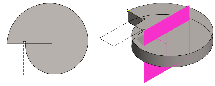
Boss > Extrude > To Selected Point
-
Click to a point. (See figure on the left).
-
OK.
Hide the auxiliary Plane, if you don't want it to appear
-
Select an auxiliary plane from the feature tree.
-
Right-click function: Hide.
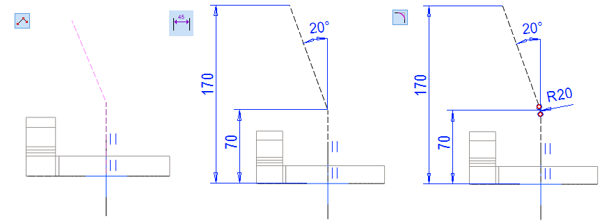
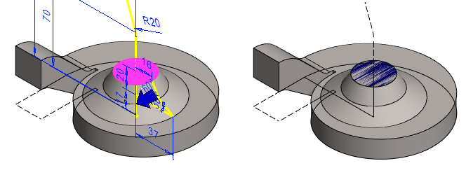
Model the pipe exit cone and the control curve
-
Right-click function: New Sketch > To vertical (XZ) plane.
Sketch the shape
-
Sketch a polyline and dimension it.
-
Select the Guide line style.
-
Click to the start point from the origo.
-
Select the horizontal line of origo as the starting element for vertical dimensions (if the program refuses to select it when the sketch is perpendicular, rotate the model slightly, e.g., drag the model slightly down with the mouse middle button).
-
-
Make a rounding between the lines.
-
Function: Round.
-
Click lines.
-
Enter the radius: 20.
-
-
Select the rounding line and change its style to Guide line.
-
Sketch a cross-section of a double cone.
-
Function: Polyline.
-
Select the Shape line style.
-
Click the first point to the guide line and use directional locks if necessary.
-
Dimension the sketch of the cross section.
-
Be sure the vertical line is aligned with the line on the guide line. If not, add a coincident constraint between the lines.
-
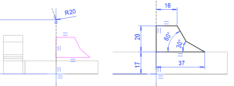
Operation
-
Boss > Revolve.
-
Accept default: 360 degrees.
-
-
OK.
-
Click the axis of rotation to the vertical line or vertical guide line of the sketch, or two points on the vertical line.
Create a cross section for sweeping
The surface in the model cannot be used for sweeping. A separate cross-section and control curve are required for sweeping. Here, the cross section is made by a sketch feature, whereby the size of the cross section changes if the dimension of the cone of the previous stage changes.
-
Click the top surface.
-
Right-click function: Sketch Feature.
-
The program opens the dialog Extrusion Data.
-
-
Select: Cross Section.
-
OK.
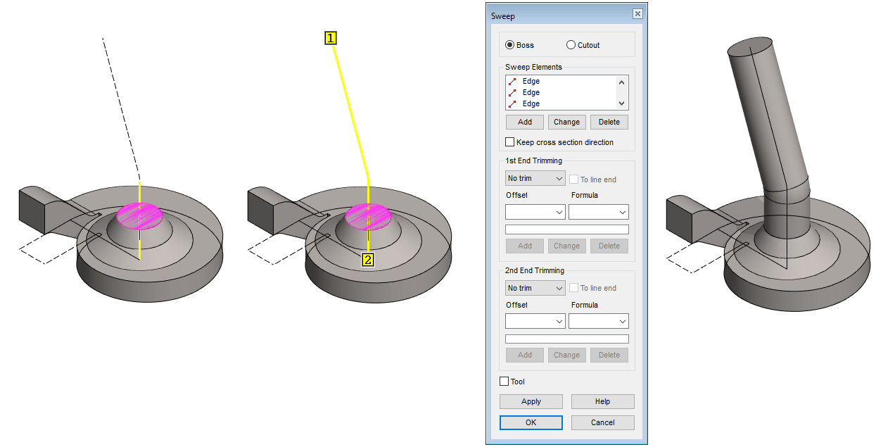
Model the internal shape of the pipe
-
Click the cross section and guide line. (Remember
-
Right-click function: Sweep > Boss.
-
The program opens the dialog Sweep and searches for lines tangential to the selected guide line.
-
-
OK.
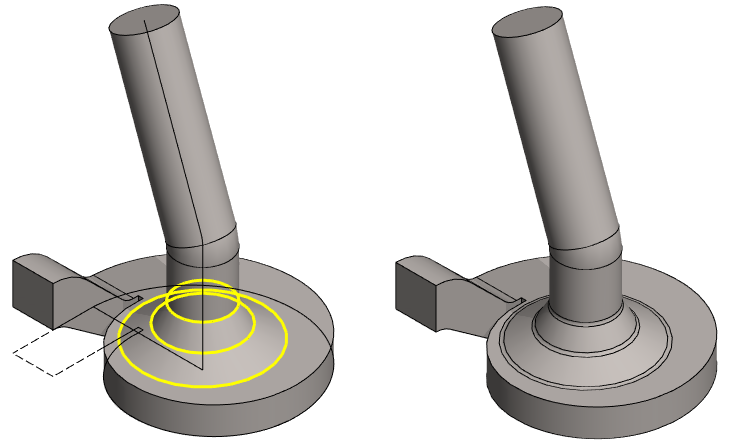
Add roundings around the pipe
-
Choose three lines. (Look at the figure).
-
Right-click function: Add Round/Bevel > Round.
-
The program opens the dialog Round.
-
-
Enter the radius: 4.
-
OK.
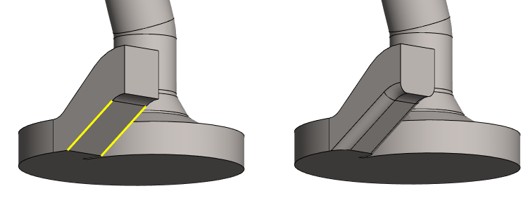
Add roundings to the underside of the cam
-
Choose two lines. (Look at the figure).
-
Right-click function: Add Round/Bevel > Round.
-
The program opens the dialog Round.
-
-
Enter the radius: 5.
-
OK.
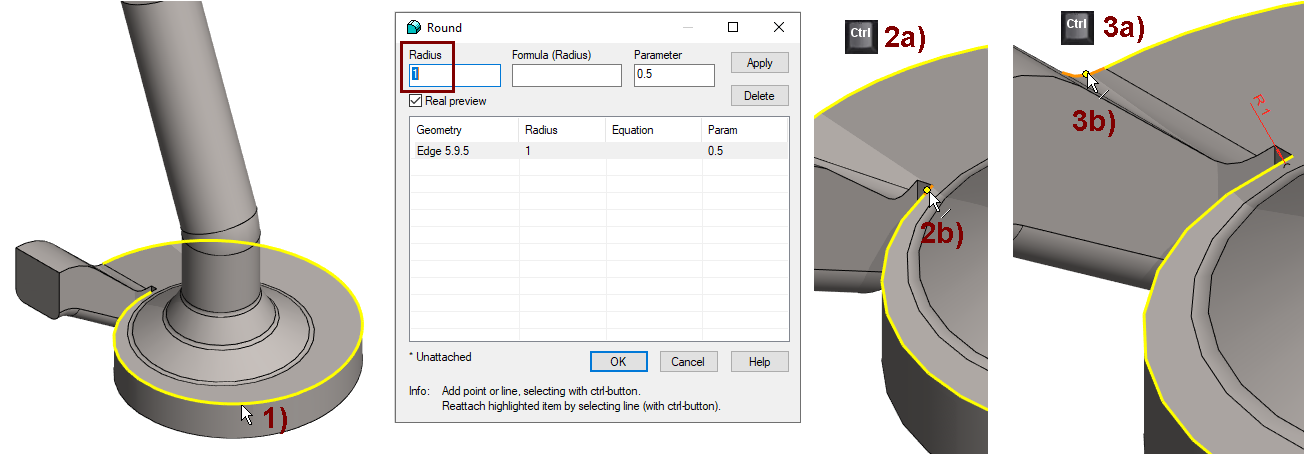
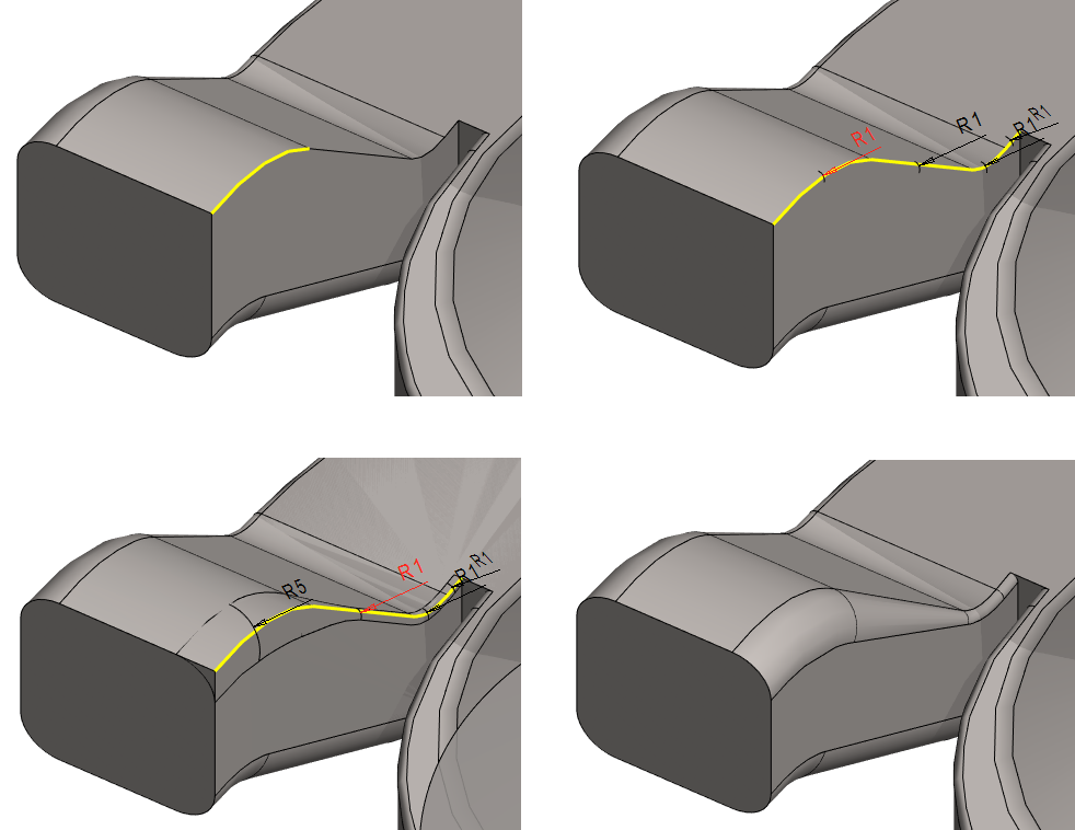
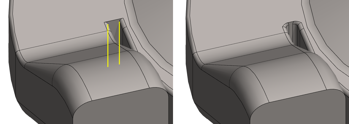
Add rounding with variable radius to the outer edge of the top surface.
-
Select a line. In the figure 1).
-
Right-click function: Add Round/Bevel > Round.
-
The program opens the dialog Round.
-
Because the selected spiral line and the lines attached to its ends are not tangential to each other, the program itself cannot find the line chain forward, so the program must be assigned continuous lines.
-
-
Enter the radius: 1.
-
Hold down the Ctrl key and click to the short line coming from the end of the spiral. In the figure 2a) and 2b).
-
Hold down the Ctrl key and click to the arc line coming from the end of the spiral. In the figure 3a) and 3b).
-
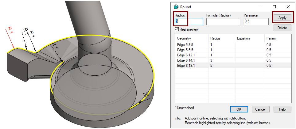
The program searches for a tangential line chain and suggests a 1mm rounding radius for all lines.
-
-
In the dialog, select the row that colors the last dimension red. (Look at the figure).
-
Enter a new value: 5.
-
Press the Apply button (to save the rounding and at the same time test the creation of the rounding and draw the rounding on the model if it succeeds).
-
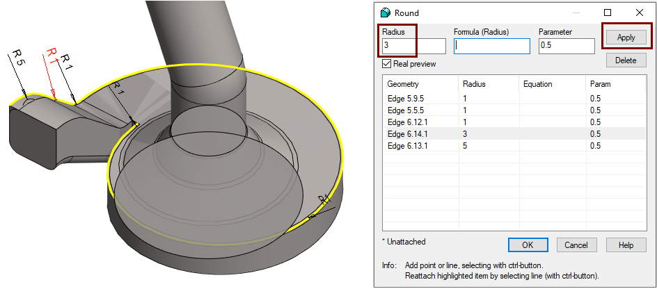
In the dialog, select the row that colors the second last dimension red. (Look at the figure).
-
Enter a new value: 3.
-
Press the Apply button
-
Here, pressing the Apply button is optional if you select the OK button after entering a new radius value.
-
-
OK.
Add a variable radius rounding to the upper inner edge of the cam
-
Click the line.
-
Right-click function: Add Round/Bevel > Round.
-
The program opens the dialog Round.
-
-
In the dialog, select the row that colors the first dimension red. (Look at the top row figure on the right).
-
Enter a new value: 5.
-
Press the Apply button (to save the rounding and at the same time test the creation of the rounding and draw the rounding on the model if it succeeds).
-
In the dialog, select the row that colors the second dimension red. (Look at the upper row figure on the left).
-
Enter a new value: 3.
-
OK.
Add the last rounds
-
Choose two lines.
-
Right-click function: Add Round/Bevel > Round.
-
Enter a new value: 3.
-
OK.
Save the model
-
File > Save or click


Exercise 14: Casting molds
This exercise was carried out with version 27.0 (Vertex 2021).
In this exercise you will learn to
-
Modeling a plane spiral.
-
Using a sketch feature to model a cross section.
-
Modeling rounding chains when edges are added to the chain.
-
Making variable radius rounding.
Functions to be used:
-
Sketching: Circle, arc with three points, two-point line and polyline.
-
Sketching: Diameter, radius, distance, dimension and tangential constraints.
-
Sketching: Round
-
Operation: Cross Section, guide curve, extrude, revolve and sweep.
-
Spiral (On a plane).
-
Add Round/Bevel > Round.
This exercise follows the modeling of the inside of a casting (water pump) like the one below. But the shape and dimensions have been invented.
Create a new part
-
File > New > Part.
-
Enter the label (which is also the name of the model and by default will be the name of the drawing).
-
Enter the archive information by clicking Arc.Data.
-
Select the project where the model will be saved.
-
OK.
-
Model a circular cross section
-
Right-click function: New Sketch > To horizontal (XY) plane.
Sketch the shape
-
Draw a circle. Use a Shape line style.
-
Point to the center of the origin of the sketch.
-
-
Draw other geometry. Use the Guide line style.
-
Add Dimension Constraints (or Diameter and Distance Constraints) as shown.
-
Add a tangential constraint between a short vertical line and a circle.
Operation
-
Cross Section.
If the program does not allow a cross-sectional operation, then perhaps some of the line is drawn with a shape line.
-
Turn them into guide lines.
If, after the operation, the desktop appears empty, the reason is that the auxiliary geometry is hidden.
-
To display the auxiliary geometry, press G or use the toolbar's Show Reference seometry function.
Model the spiral
-
Click the cross section.
-
Right-click function: Add Spiral.
-
The program opens the dialog Spiral.
-
-
Enter the number of threads: 1.
The program uses the radius of the circular cross section as the radius of the beginning, and sets the radius of the end to zero, i.e. the center of the circle.
-
If the direction of the spiral is Clockwise, change the direction to Counterclockwise.
-
Select End radius.
-
Enter the end radius: 68.
-
Point to the location of the starting point of the spiral at the lower end of the short vertical guide line. (Look at the picture).
-
OK creates a spiral.
Model the base
-
Right-click function: New Sketch > To horizontal (XY) plane.
Sketch the shape
-
Copy lines to the sketch plane.
-
Function: Copy lines or
-
Right-click function: Line > Copy to Sketch Plane.
-
-
Select the Guide line style.
-
Click the lines you want to copy.
-
Give the Ready command with:
-
-
-
Use the Delete Section function to remove extra parts of the lines.
Operation
-
Boss > Extrude: 17.
Make a new sketch using the auxiliary plane and point
-
Return the Lateral (YZ) plane if it is hidden.
-
Select the hidden auxiliary plane: Lateral (YZ) plane.
-
Right-click function: Restore.
-
-
If necessary, change the size of the auxiliary plane.
-
Click the auxiliary plane.
-
Right-click function: Change Size. (Ex. 80).
-
-
Select the auxiliary plane and the corner point (shown in the figure) (Remember the
-
Right-click function: New Sketc.
If you have the sketch option Perpendicular selected, the program will turn the part upside down.
-
In that case, select Isometric View from the tool strip.
Model the cam
Sketch the shape
-
Sketch and dimension a rectangle.
-
Select the Contruction line style.
-
Click to the first two points of the control curve endpoints.
-
Add dimension constraint: 50.
-
Sketch two tangential arcs with the function: Arc with three points.
-
Click the starting point of the arc so that the upper horizontal line with the point is colored with attention color. (You get tangentiality to the arc).
-
Click the starting point of the second arc so that the horizontal line of the origo and the point is colored with attention color.
-
-
Skecth a Two-Point line between the endpoints of the arcs.
-
Add a tangential constraints between the line and the arcs.
-
Add radius constraints.
-
Lower arc: 10.
-
Upper arc:: 30.
-
-
Sketch and dimension the horizontal construction line.
-
Distance to the top: 25.
-
-
Sketch the shape of the lower surface of the cam using an arc with tree points and a two-point line.
-
Select the Shape line style.
-
-
Add a tangential constraints between the line and the arcs.
-
Add a
coincident constraint
between the lower period of polyline and the guide line.
-
Add the radius constraint of the arc (15) and the distance constraint of the lower line (10).
Close the shape by adding two vertical two-point lines.
-
Right-click function: New Sketch > To vertical (XZ) plane.
Operation
-
Boss > Extrude > To Selected Point
-
Click to a point. (See figure on the left).
-
OK.
Hide the auxiliary Plane, if you don't want it to appear
-
Select an auxiliary plane from the feature tree.
-
Right-click function: Hide.
Model the pipe exit cone and the control curve
-
Right-click function: New Sketch > To vertical (XZ) plane.
Sketch the shape
-
Sketch a polyline and dimension it.
-
Select the Guide line style.
-
Click to the start point from the origo.
-
Select the horizontal line of origo as the starting element for vertical dimensions (if the program refuses to select it when the sketch is perpendicular, rotate the model slightly, e.g., drag the model slightly down with the mouse middle button).
-
-
Make a rounding between the lines.
-
Function: Round.
-
Click lines.
-
Enter the radius: 20.
-
-
Select the rounding line and change its style to Guide line.
-
Sketch a cross-section of a double cone.
-
Function: Polyline.
-
Select the Shape line style.
-
Click the first point to the guide line and use directional locks if necessary.
-
Dimension the sketch of the cross section.
-
Be sure the vertical line is aligned with the line on the guide line. If not, add a coincident constraint between the lines.
-
Operation
-
Boss > Revolve.
-
Accept default: 360 degrees.
-
-
OK.
-
Click the axis of rotation to the vertical line or vertical guide line of the sketch, or two points on the vertical line.
Create a cross section for sweeping
The surface in the model cannot be used for sweeping. A separate cross-section and control curve are required for sweeping. Here, the cross section is made by a sketch feature, whereby the size of the cross section changes if the dimension of the cone of the previous stage changes.
-
Click the top surface.
-
Right-click function: Sketch Feature.
-
The program opens the dialog Extrusion Data.
-
-
Select: Cross Section.
-
OK.
Model the internal shape of the pipe
-
Click the cross section and guide line. (Remember
-
Right-click function: Sweep > Boss.
-
The program opens the dialog Sweep and searches for lines tangential to the selected guide line.
-
-
OK.
Add roundings around the pipe
-
Choose three lines. (Look at the figure).
-
Right-click function: Add Round/Bevel > Round.
-
The program opens the dialog Round.
-
-
Enter the radius: 4.
-
OK.
Add roundings to the underside of the cam
-
Choose two lines. (Look at the figure).
-
Right-click function: Add Round/Bevel > Round.
-
The program opens the dialog Round.
-
-
Enter the radius: 5.
-
OK.
Add rounding with variable radius to the outer edge of the top surface.
-
Select a line. In the figure 1).
-
Right-click function: Add Round/Bevel > Round.
-
The program opens the dialog Round.
-
Because the selected spiral line and the lines attached to its ends are not tangential to each other, the program itself cannot find the line chain forward, so the program must be assigned continuous lines.
-
-
Enter the radius: 1.
-
Hold down the Ctrl key and click to the short line coming from the end of the spiral. In the figure 2a) and 2b).
-
Hold down the Ctrl key and click to the arc line coming from the end of the spiral. In the figure 3a) and 3b).
-
The program searches for a tangential line chain and suggests a 1mm rounding radius for all lines.
-
-
In the dialog, select the row that colors the last dimension red. (Look at the figure).
-
Enter a new value: 5.
-
Press the Apply button (to save the rounding and at the same time test the creation of the rounding and draw the rounding on the model if it succeeds).
-
In the dialog, select the row that colors the second last dimension red. (Look at the figure).
-
Enter a new value: 3.
-
Press the Apply button
-
Here, pressing the Apply button is optional if you select the OK button after entering a new radius value.
-
-
OK.
Add a variable radius rounding to the upper inner edge of the cam
-
Click the line.
-
Right-click function: Add Round/Bevel > Round.
-
The program opens the dialog Round.
-
-
In the dialog, select the row that colors the first dimension red. (Look at the top row figure on the right).
-
Enter a new value: 5.
-
Press the Apply button (to save the rounding and at the same time test the creation of the rounding and draw the rounding on the model if it succeeds).
-
In the dialog, select the row that colors the second dimension red. (Look at the upper row figure on the left).
-
Enter a new value: 3.
-
OK.
Add the last rounds
-
Choose two lines.
-
Right-click function: Add Round/Bevel > Round.
-
Enter a new value: 3.
-
OK.
Save the model
-
File > Save or click